- Eventually, the more complicated Diplexer built for 40-80 meter bands with more LC traps. It is the 5th order Diplexer with all improved parameters.
- The 5th order Diplexer has better than -40dB of band Isolation with very low Insertion Loss below 0.1dB
- Please, see graphs and numbers in a Low Power 40-80 Diplexer Specification.
- This is a link to a DX Engineering website.
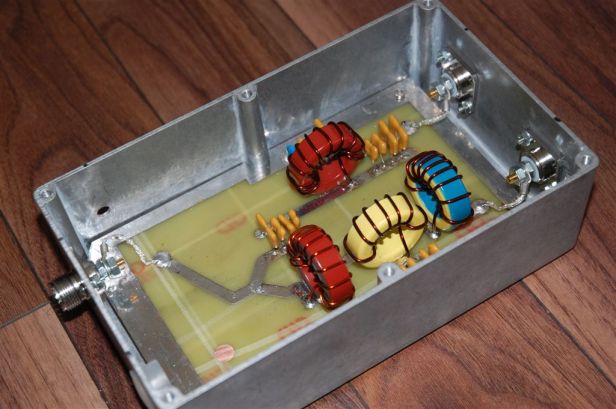
Below shown the 3rd order 40/80 Diplexer.
The design is a combination of LPF and HPF circuits with LC traps for 40 and 80 meter bands to increase band isolation.
- When you have LPF and HPF type Diplexer, the only BPFs will provide band isolation for other bands because Diplexer has no attenuation above and below 80 and 40 meter bands.
- As an example, Diplexer has no 20M band attenuation for 40M band port (HPF) and Diplexer has no 160M band attenuation for 80M band(LPF). The only attenuation for those bands, in the example above, is from connected BPFs.
Some numbers achieved for 200 watt diplexer:
- Insertion Loss (IL) < 0.1dB.
- Band Isolation > -35dB for 40M band
- Band Isolation > -30dB for 3.5-3.8 MHZ (lower isolation above 3.8MHz)
- Return Loss (RL) > 27dB
- 100 watt output power with 100% cycle
- 200 watt output power PEP
Please, see schematics below – a Cauer (Elliptic) type.
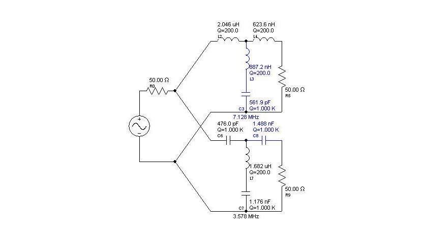
Please, see schematics below – a Chebyshev type.
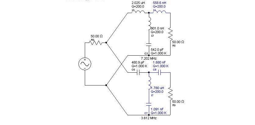
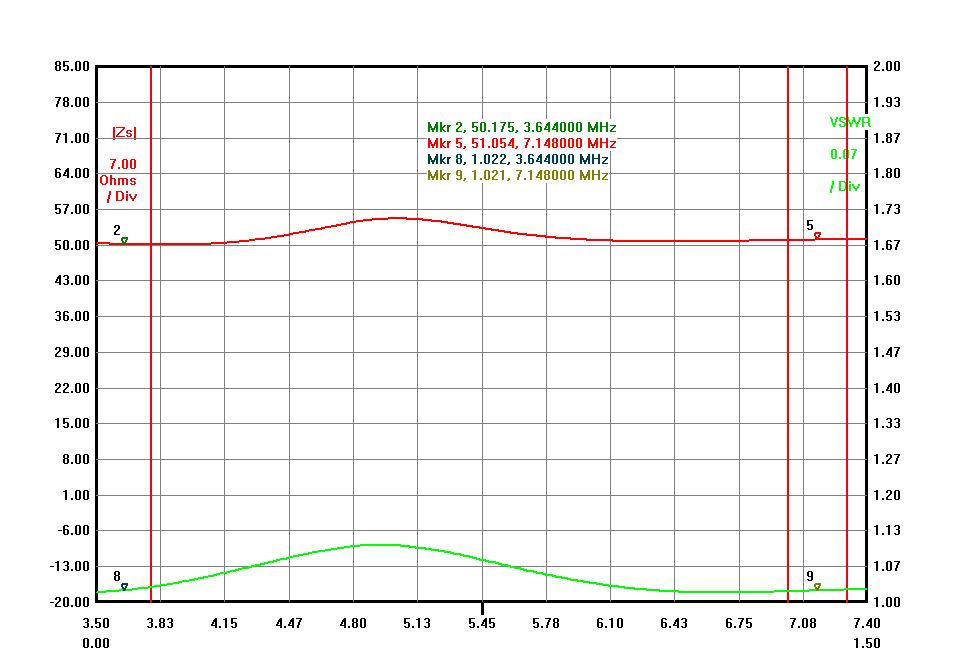
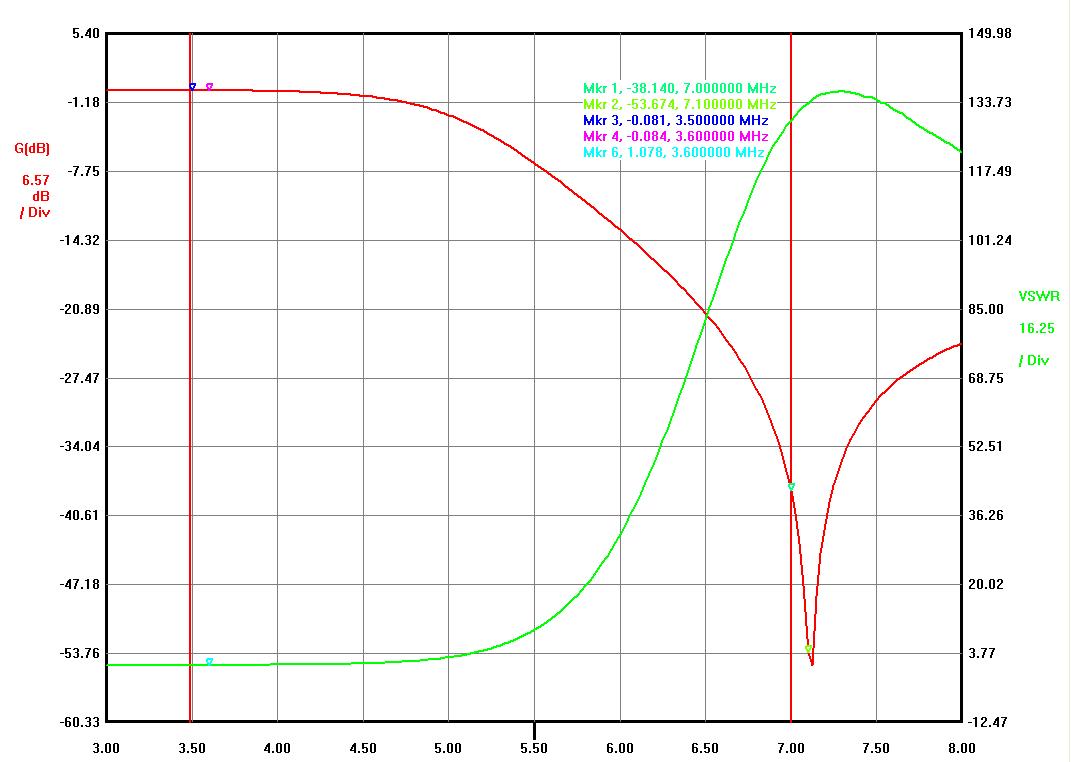
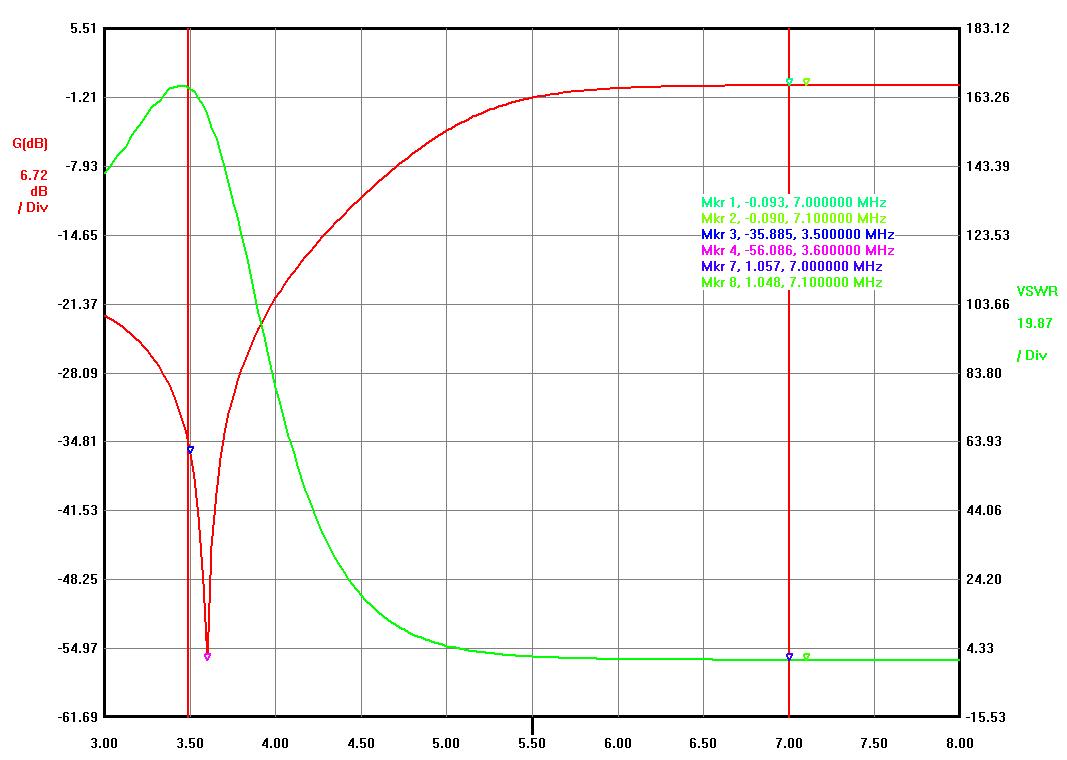
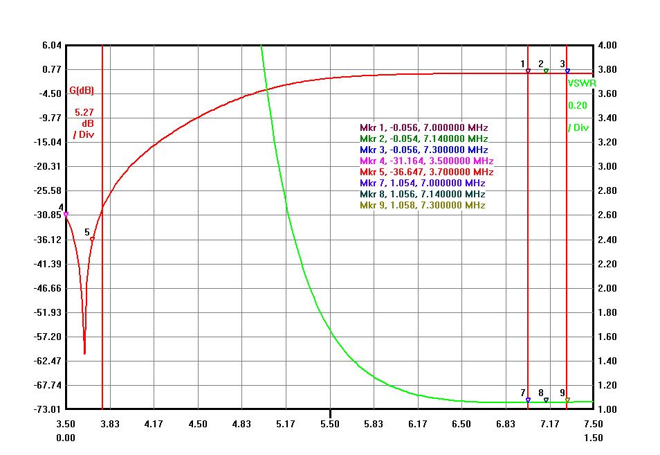
Please, see Diplexer low power graphs below built based on a Cauer type.
- The difference between filter types is not a significant to discuss but two schematics allows to chose more suitable capacitor’s values.
Below is a High Power Diplexer for 40 and 80 meter rated at 3000 watts of an amplifier output power.
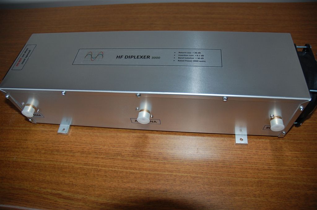 Insertion Loss (IL) < 0.08dB
- Band Isolation > -35dB for 7.0-7.3 MHz
- Band Isolation > -30dB for 3.5-3.8 MHZ
- Return Loss (RL) > 30dB
- 1500 watt output power with 100% cycle no cooling required
- 3000 watt output power (50 CFM cooling fan recommended)
- 1411ZU 17″ x 5″ x 4″ Hammond enclosure
The 40M band below:
The 80M band below:

Graph below is an Impedance ([Zs]) and VSWR from Antenna port: