- Part List
- Assembly And Tuning Instructions
- 40-80-160 Low Band Triplexer
- 20M Low Power BPF
- 10M Low Power BPF
- 200W Triplexer with BPF set
- 200W Band-pass Filters
Tribander antenna together with the Triplexer with BPFs setup should bring no interference at all between bands, except 2nd harmonics from 20M TX to 10M RX, like 14025KHz TX will give 28050 KHz 2nd harmonics signal.
The harmonics level depends mostly on an Antenna type (No LC trap antennas are better in this term). With bad LC trap on a tribander antenna, the 2nd harmonics can cover the entire 10M band up to S3-S4 noise level.
Tribander without LC traps behave much better in this term.
Please, listen how Triplexer with BPFs sounds on most difficult bands, 20 and 10 meter bands. This is OR2F and ON5RA as OT70OSB with their WRTC-2018 equipment (Low power BPFs with VA6AM HP Triplexer).
- Channel L – FT-1000MP, Pout = 120W, QRG= 14216 KHz fixed
- Channel R – Elecraft K3, Pout = 110W, QRG= S&P 10m band (CW + SSB)
- After 03:38 from beginning of the file, 10M band switched to SSB and you can hear the harmonics noise increased.
- They were able to work stations +- 5KHz from harmonics around 28432 KHz frequency.
10 and 20 meter bands audio file
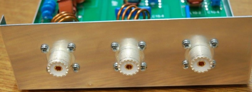
Pictures below are for 1590F. This is for an old triplexer PCB version where PCB installed on UHF connectors (not in production anymore).
Below is two triplexers in Hammond 1411 series boxes 8″(1411RU) wide.

- Since the end of 2013 when I’ve started this triplexer project. Triplexer design has been the best one by all parameters.
- Please, remember that good band isolation is not a problem to achieve for the triplexer design . You will get it simply turning LC trap inside the band.
- The best possible Return Loss (SWR) and the lowest Insertion Loss are more difficult parameters to achieve and these parameters are to pay attention to.
Recommended applied power with antenna VSWR <1.5 to every band port:
- 200W – ICAS
- 100W – 100% key Down Duty Cycle
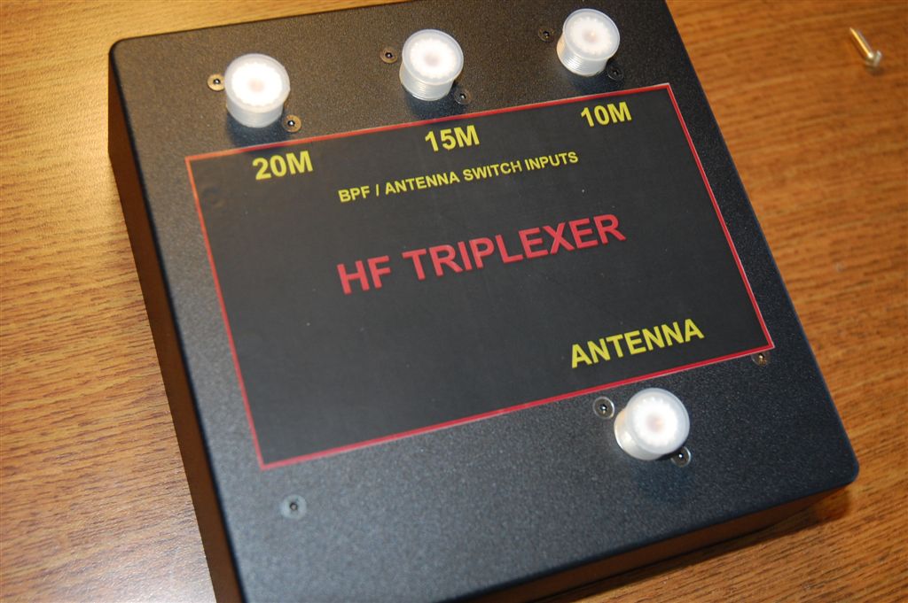
Triplexer converts a single feed line from a tribander, multiband vertical or wire antenna into 3 independent bands allowing to transmit and listen on different bands the same time.
It can be a valuable addition to the station in SO2R and Multi-Op contesting, Field Day operations, DX-peditions and in many other events.
- Triplexer together with band-pass filters allows you to transmit and listen on different bands simultaneously.
The idea to have a triplexer with a good isolation came to me when I realized that -27dB attenuation between 10 and 15 meter bands in my 28MHz BPF (5B4AGN design) is not sufficient number. I think at least -60dB is required between bands to work comfortably and safely in a SO2R single tribander 100-150 watt station setup. So, I need a good triplexer that would give me another 30-35dB attenuation to addition what I’ve had from BPF.
I started project in 2013 by checking internet and found no triplexer that has this level of attenuation. No, I found one from 4O3A, but it is an expensive one because built for a high power setup. The only option left is to build my own triplexer. Later, I found 4O3A triplexer weak points as well. Please, see some numbers.
Before starting my triplexer project, I tried to find any idea of a triplexer practical implementation on a web.
I found only one article “HF Yagi Triplexer Especially for ARRL Field Day”, and I liked that triplexer simplicity, but the result I got from it was not good at all. High insertion loss(IL), low band attenuation and high SWR turned it out as a simple one day project for fun, but not what I would like to see on my station as a contesting device.
- Triplexer is a more complicated gear if you would like to have a good one.
INRAD builds a better one than that described in an article, but some attenuation numbers missed my requirements and I found a few cases when INRAD triplexers failed (Two of INRAD triplexers failed on WRTC-2014 team competition).
Table shows only lower parameter values. (14-14.35, 21-21.45, 28-28.8)
| Name | VA6AM | Inrad | Dunestar | RA6LBS |
| VSWR | <1.1 | No Data | No Data | <1.2 |
| Insertion Loss(dB) | <0.15 | <0.25 | <0.35 | <0.3 |
| 20M Isolation(dB) | >30 | >25 | >12 | >30 |
| 15M Isolation(dB) | >33 | >20 | >12 | >25 |
| 10M Isolation(dB) | >30 | >20 | >12 | >30 |
All data is from a company’s websites. I compare 4O3A triplexer with VA6AM on a High Power triplexer page.
RA6LBS triplexer is quite good but the 15M band has some low numbers for Insertion Loss (0.3 dB) and VSWR (1.2) and 15M band tuning is very sharp. It looks like there is the same problem with 15M band as 4O3A combiner has. The Insertion Loss IN-Band graph should be almost a straight line. Please, see graphs below or 15M In-Band graph made for a high power triplexer.
With such a sharp tuning as the RA6LBS triplexer has on the 15M band it is very difficult to balance all triplexer band legs on an antenna port.
Please, see 15M band comparison with RA6LBS triplexer graphs below.
- The vertical and horizontal scales are the same for comparison.
- VA6AM 15M graphs at the bottom, left graph is VSWR and right graph is for Insertion Loss.
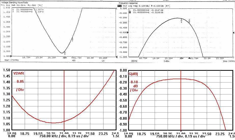
You can see how much wider VA6AM triplexer 15M band by Insertion Loss and VSWR. Wider means more stable parameters if any changes happen, such as capacitance, inductance or temperature changed.
BandPass range By VSWR better than 1.2
- VA6AM 18.4-22.4 MHZ (4 MHz)
- RA6LBS 20-21.45 MHz (1.45 MHz)
BandPass range By Insertion Loss below -0.3 dB
- VA6AM 19-22.6 MHZ (3.6 MHz)
- RA6LBS 20-21.45 MHz (1.45 MHz)
If you plan to build triplexer by your own, please pay attention to numbers shown above.
- The triplexer central frequency is 20MHZ. This is how a software calculated it and there is some sense to do this way to have the same isolation between 15 and 10 meter bands as it is between 15 and 20 meter bands.
- If the triplexer central frequency moved to 21MHz it will increase isolation of 20M band to -35dB and decrease 10M band isolation to -25dB.
- 15M band triplexer leg is quite wide by parameters and it allows to have good VSWR, Insertion Loss and Return Loss for this band despite the fact that triplexer tuned for 20MHz.
Some numbers I achieved for the new designed triplexer:
- Insertion Loss (IL) < 0.15dB
- Band Isolation > -30dB. I got better than -40dB attenuation between 10 and 20 meter bands.
- Return Loss (RL) > 26dB. It means there is no SWR higher than 1.1 on all bands.
- 100 watt output power with 100% cycle
- 200 watt output power PEP
Every 0.1dB of insertion loss is 2.5% power loss. 0.4dB loss of Dunestar triplexer is 10% of power loss.
- The higher the IL the more heat dissipated on the triplexer parts and as a result the reliability under the question.
Low Insertion Loss was important to consider during a design stage. For contesting in a Low Power category every single watt should be counted. The power get lost in your tuner, triplexer, filters, switches, cables, connectors and SWR is never equal to 1, it’s easy to go down from 100 to 60-70 watts actually working for you.
- This is the first project on the Web which provides all required information to build triplexer by yourself.
Triplexer consists of LPF, HPF and BPF Cauer type filters. Please, see triplexer schematics below.
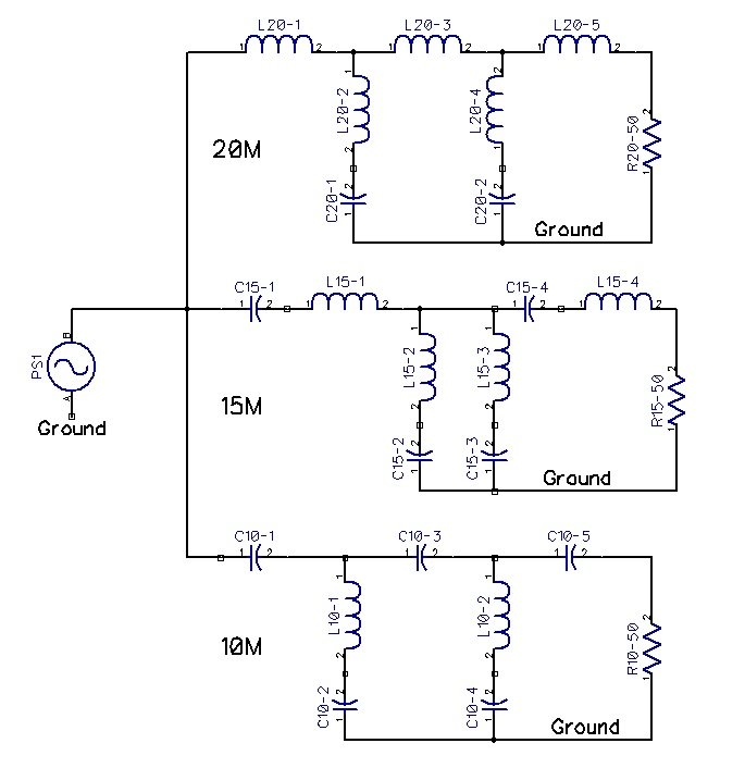
Every band filter has LC traps for other bands, such as 10M HPF has LC traps for 21MHZ and 14MHz, 20M LPF has LC traps for 21MHz and 28MHz and 15M BPF has LC traps for 14MHz and 28MHz. Band traps allow to achieve a very good band isolation.
The weakest component where triplexer or BPF can fail is a capacitor.
You can use Silver Mica or ceramic type capacitors in parallel (3 or better 4-5 of them).
I am using so many in parallel ceramic/Mica capacitors are not only for reliability purpose but also to make it easier to get capacitor required values. How to make 96pF with two capacitors only? It is easier with three of them and basically no problem at all if you use four capacitors.
- Triplexer tested with 100 watt continuous tone for a few minutes with no overheating at all. The test was done with SWR close to 1.8:1.
- All unused band ports should be connected to 50 Ohm loads to get maximum from the design. Triplexer is the balanced filter system and should have all ports loaded evenly for the best reliability and performance.
- You can build such an antenna switch on KK1L switch PCB (-67dB minimum port isolation) or you can buy a 2×6 switch with interlocking system from RemoteQTH.com (-71dB minimum port isolation) .
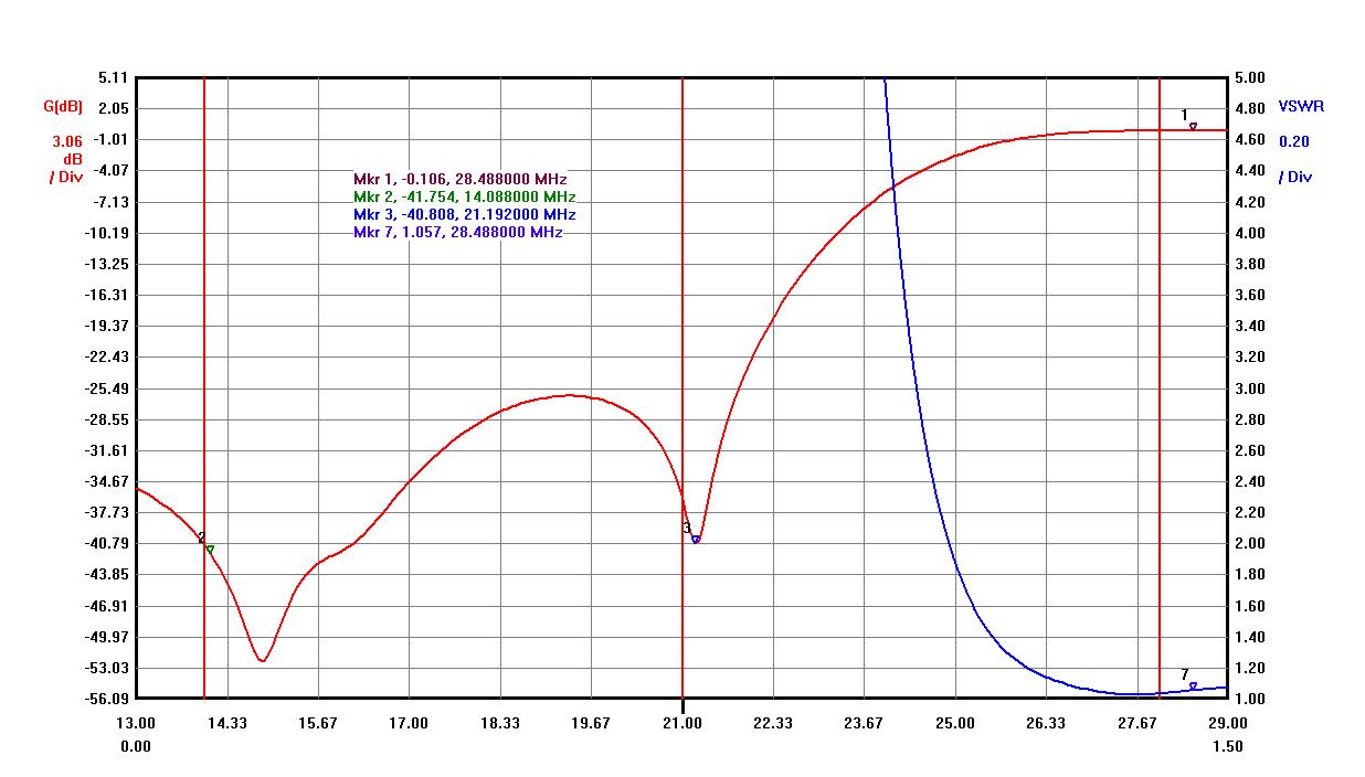
10M band measurements:
- Insertion Loss: less than 0.13dB
- SWR: better than 1.1
- 15M attenuation: better than -33dB
- 20M attenuation: better than -40dB
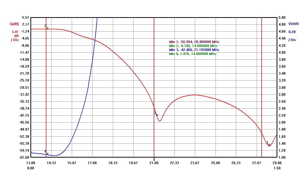
20M band measurements:
- Insertion Loss: less than 0.13dB
- SWR: better than 1.1
- 15M attenuation: better than -36dB
- 10M attenuation: better than -47dB
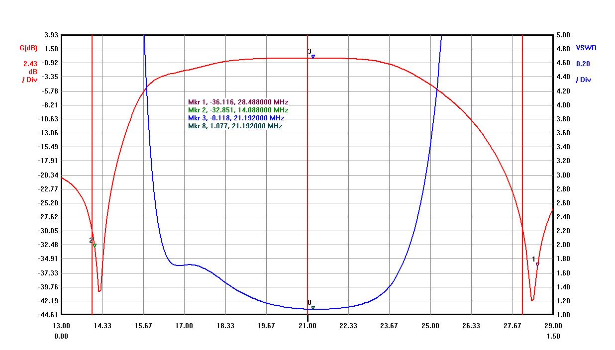
15M band measurements:
- Insertion Loss: less than 0.13dB
- SWR: better than 1.1
- 20M attenuation: better than -30dB
- 10M attenuation: better than -30dB (28-28.8 MHz)
- During your normal operation use all connection cables between triplexer and your BPFs or your antenna switch as short as you can for the best band isolation ( especially for 10M band)
- NEVER USE TRIPLEXER WITHOUT BANDPASS FILTERS CONNECTED !!!
- You can burn LC traps if a transmission power applied to a wrong band port. Please, be careful !!!
- SW9AA team had a very good result in 2018 CQWW CW in M/S Low Power category using VA6AM Triplexer. Some more info can be found at 3830 Score page.
- LY9A/LY4L are the winners of WRTC-2018 who used VA6AM 1500W Triplexer and BPFs set. Congratulations!
- It was nice to see Big Thanks from young WRTC team YO8TTT-UT5GW.
- I’ve been counting how many teams could use my triplexer design for coming WRTC-2018 championship in Germany …. 23 as per my best knowledge on Feb 19, 2018 .
- DK3WE won the 1st place in 2015 CQWW CW QRP using a bare-foot-no-BPF attached VA6AM triplexer.
- There are more than 400 Low Power Triplexers built as I’ve known of and no single failure has been reported yet. If any problem experienced, please let me know the issue to make the triplexer better.
