- Please, remember that triplexer must see 50 Ohm load on every triplexer port during an adjustment process. You need two 50 Ohm dummy loads as two other band ports connected to your VNA.
- Please, see all graphs published on a Triplexer main webpage as a reference to a desired final result.
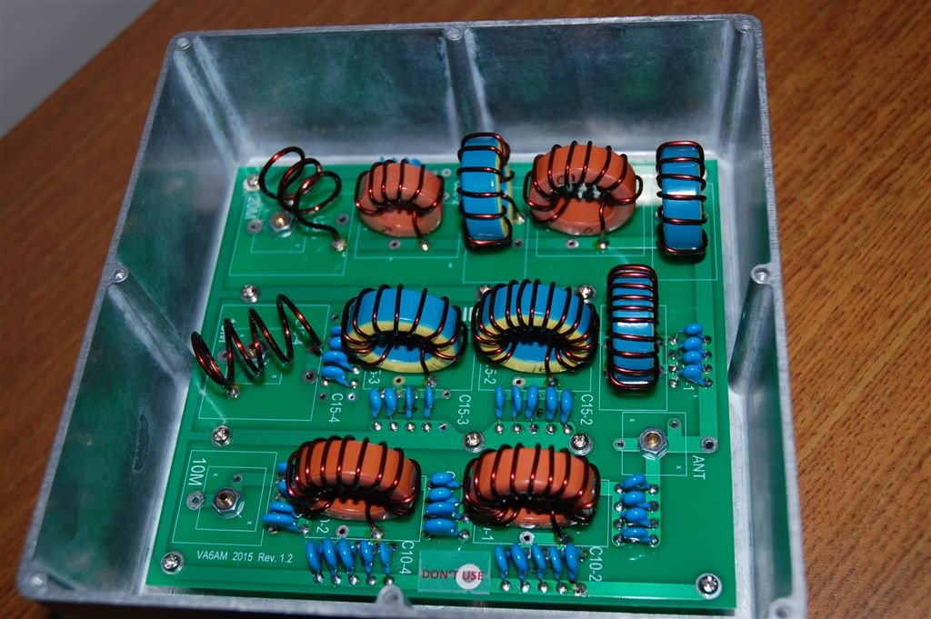
All photos made with 1590F Hammond enclosure. Now, Hammond 1411RU enclosure is used.
- The first step is to use an empty triplexer board as a template to make all required enclosure holes. 9 of them for standoffs and four large 16mm in diameter holes for connectors. You need another 8 or 16 holes to secure connectors on the enclosure.
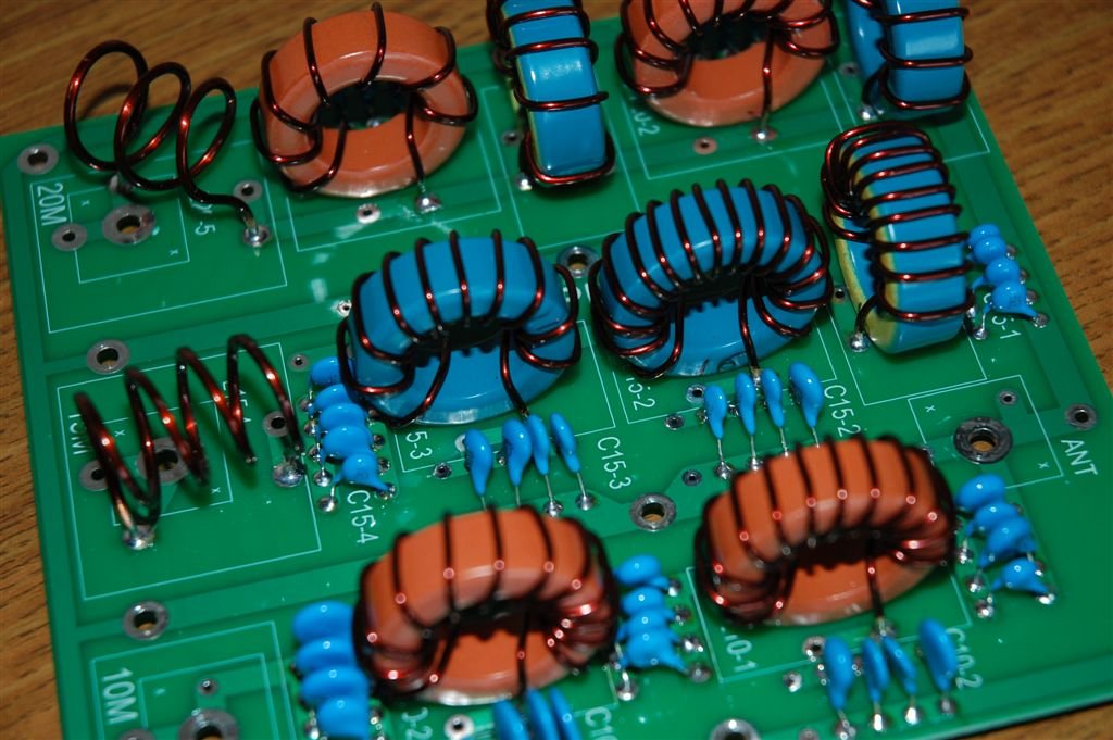
The board requires good grounding to perform as expected.
- Please, never try to tune the triplexer without been installed into the enclosure.
After triplexer assembly completed and board installed it is a time for tuning the triplexer.
If toroid coils are good and capacitor values are close to required values, the procedure is quite easy with a VNA as a helper. I would try to give some recommendations based on my experience.
- I am using two-detectors N2PK VNA with a Reflection Bridge. It allows me to see Insertion Loss and SWR(Return Loss) the same time (Transmission and Reflection mode simultaneously). I connect Reflection Bridge output to a triplexer band port and the 2nd VNA detector to the triplexer antenna port.
- Do not forget to terminate unused band ports with 50 ohm loads. Sometimes, especially for 10M band if your load is some kind of Dummy Load connected to triplexer by a coax cable, the actual SWR is never close to 1. As a result you can expect a bad SWR for the triplexer measurements.
- The best way is to use a 50 ohm load connected to the triplexer connector directly. You can solder a regular non-inductive 50 ohm resistor on the board as well.
Step 1. Always start tuning with LC trap adjustments. Change inductance to get LC trap frequencies as close to calculated values as possible.
- LC trap tuning should be made using VNA. The Tansmission graph will tell you where the resonances located.
Spreading turns will change frequency up and compressing will change it down. Please, adjust all LC traps before you start any triplexer band SWR or Return Loss tuning.
- LC trap resonance frequency values influence all triplexer parameters.
If you move LC trap frequency away from calculated value, you have to adjust another LC trap to find a new balance for the band.
- 0.2-0.3% frequency change is a very safe margin for LC trap frequency adjustments. 0.1% is 21 KHz for 15M band, as an example.
- Please, do not be confused by software calculation and feel confident to adjust LC trap resonance if it brings some improvements for parameters.
- The rule of thumb here is to keep SWR and Insertion Loss low while changing LC trap peak point.
You can do some test. Please, adjust LC trap frequency as calculated, than change one LC trap frequency (any direction) to see how SWR and IL changed. After that, change another the same band trap frequency to see if you can simply return SWR and IL back to values before the test. You can see than doing that you can improve parameters of the particular band or get it worse. It is a good idea to do it to every band filter to understand if you have the maximum from the triplexer.
- After setting all LC trap frequencies you can go to Step 5 below to tune from antenna port where all band connected to each others or go to Step 2.
Step 2. I recommend to tune 10M LC traps after 15 and 20 meter bands have good SWRs.
Change LC trap frequency by spreading/compressing turns a little to get the best possible outcome. I always do it to get the best numbers even if SWR value for the band is below 1.1.
Usually, LC trap adjustments should do the job and you can achieve SWR better than 1.1 (Retrun Loss better than 26dB).
If required 20M LC trap peak for 10M band leg is quite far from 14MHZ, please do not worry. Good SWR and Isolation Loss much more important than band isolation value which will be increased by attached BPFs.
- 15M L1 and 20M L1 coils influence a 10M band Return Loss.
If 10M leg SWR is not below 1.1 you can try to change 309pF value to 330pF and 474pf to up to 550pF to improve the Return Loss.
At the very beginning, do not spend too much time trying to make each band perfect.
- Get SWR for a minimum value and reconnect your VNA to the next band….you will come back to the band later to finish the procedure.
Step 3. There is no difference what band to choose. Let’s start with 20M band. This is the most “flexible” band. LC traps usually not a problem to tune, and all the rest components left are coils. It is good as it is very easy to adjust inductance, but because of it you can get lost in all possible inductance variations.
There are 3 coils beside LC traps. I would start checking 14MHz Insertion Loss adjusting L1, L3 and L5 coils. L1 and L3 are to pay attention to at this point. Please, get the best SWR (Return Loss) adjusting L1 and L3 and L5 coils. L5 adjustment will be the last to adjust to fine the tuning.
- Please, change inductance by compressing/spreading turns by a very very little steps. I would recommend to set your VNA frequency range at 12 to 16 MHz at this stage of Insertion Loss/SWR measurements.
Step 4. The 15 meter band is different as it is actually a BPF and for a minimum Insertion Loss both L1C1 and L4C4 resonances should be as close as possible. You can measure those resonance frequencies, but I never did.
Please, use your VNA to control Return Loss for the band by adjusting those two coils, L1 and L4. 15M band BPF is a very wide filter to pay attention to its actual center frequency. As soon as you get an acceptable Insertion Loss you are good to go.
- L1 and L4 influence the peak of the Return Loss graph and you can change those coils the way that the best number located inside the 15M band.
The LC trap resonances are very sharp for 15M band and there is not too much room to play with those LC traps to improve SWR as it was with other bands. You should set -30dB attenuation at 14Mhz and at 28MHz by LC traps adjustment.
L1 and L4 coils are very sensitive to adjustments and required a very little changes at a time during tuning procedure.
- The tip is to to pre-tune L1 for the best 10M SWR and after that change the L4 coil for the best 15M parameters. 10M band good SWR is the most difficult to achieve and adjusting L1 coils for both 20 and 15 meter ban section can help with this.
Step 5. Now, if all bands are good it is time to reconnect your VNA to measure SWR from the triplexer antenna port. Now, VNA Reflection Bridge should be connected to antenna port and all band ports loaded by 50ohm.
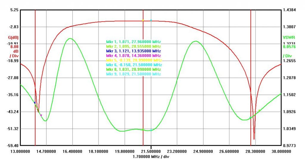
The graph below shows 15M band and SWRs (green line) from antenna port. If your triplexer balanced well SWR line is symmetrical. If it is not fully symmetrical but all parameters are within specification( IL below 0.15dB and SWR below 1.1) there is nothing to worry about.
- You can start Step 5 right after all LC trap frequencies setup but I always check it when each band tuned from each band port.
After that knowing that Antenna port balanced for all bands it is much easier to align every band port.
- It is acceptable if SWR(RL) graph is not the same symmetrical like on the graph below but you should have SWRs in a good range around 1.1 value for every band.
The triplexer specification is very good and you can have a very good triplexer even without tuning the triplexer to the maximum possible points.
- Later version of triplexer enclosure 1411RU used to have connectors on a side of the enclosure. The difference is that air coil’s one end soldered directly to UHF connector.
- Please, see a picture below in 1411RU enclosure (8″ x 6″ x 3.5″).
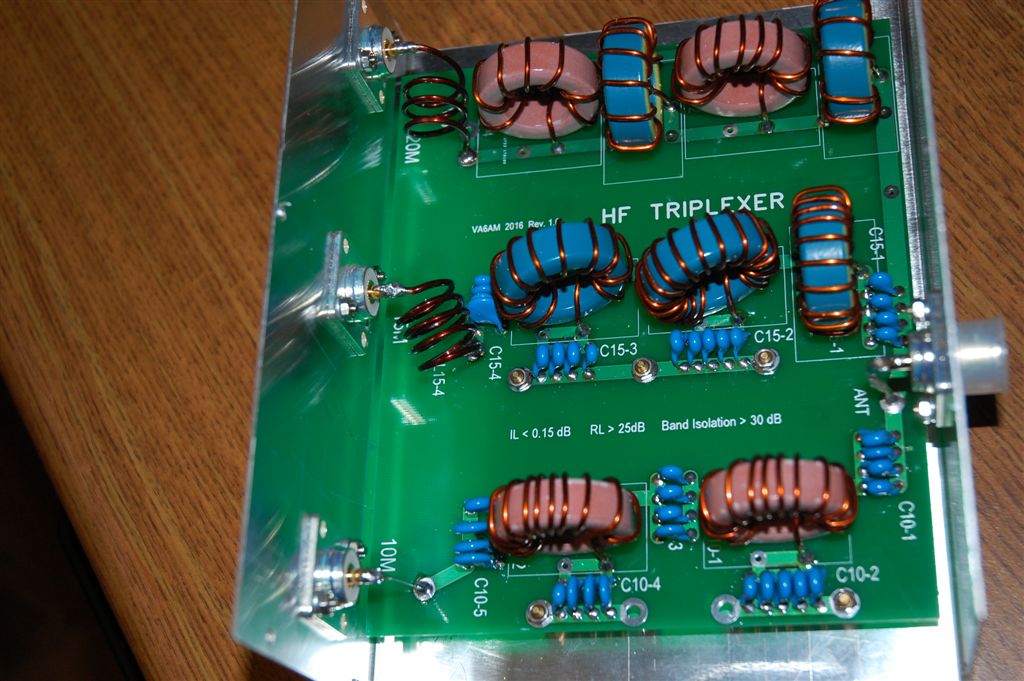
1411RU (8″ wide) and 1411UU (10″ wide) enclosures are on a photo below.

