BPFs maximum applied power is the same as for 3000W BPFs because the same parts used but triplexer built on a PCB board and is up to 2000W.
The project idea is to design and build a Triplexer with BPFs set for 1500 watt output power which is lighter and smaller than the 3000W version of the Triplexer and BPFs.
This set so-called “DX-pedition set” is easier to travel with and all boxes recommended to be installed one over another and not required a wall installation (it can be installed on a wall as well).
With total band isolation better than -75dB it can be used up to 2000W without any problems. 4O3A rated his set for 4500W ICAS having -72dB of a band isolation between 10 and 15 meter bands( from 4O3A.com).
Some numbers for -75dB of band isolation with 1500 watt output power:
- 1500W is 275V of effective voltage
- -75dB attenuation decreases voltage from 275V to 50mV
- -75dB attenuation decreases power from 1500W to 0.00005W (-13dBm)
Some short specification of the 1500W set:
- All filter boxes are smaller compare to 3000W set and built with a thicker aluminum.
- BPFs are the 4th order Chebyshev type with adjacent band isolation > – 45dB
- BPFs can be the 5th order type built in a 2″ longer enclosure with isolation > – 55dB
- BPFs together with Triplexer are better than -75dB ( – 85dB if 15 and 20 bands are the 5th order BPFs)
- Lower BPFs order allows to have a lower Insertion Loss
- More than -100 dB of isolation between 10 and 20 meter bands (with Triplexer)
- It can be used without a fan cooling up to 1500 watts (CW/SSB 50% duty cycle)
- All parts inside rated at 3500W output power
- Triplexer built on three FR-4 PCB boards
Recommended BPF Power with antenna VSWR
- With air cooling: 1500W CW/SSB /RTTY (2000W PEP)
- Without fan installed: 1000W CW/SSB/RTTY
Enclosure is Hammond 1444-1573 for 4th order BPF :
- Without Fan – 15″ x 7″ x 3″ (38 x 17.5 x 8 cm)
- With Fan Installed – 15″ x 8″ x 3″ (38 x 19.5 x 8 cm)
Longer by 2″ enclosure is Hammond 1444-1773 for 5th order BPF :
- Without Fan – 17″ x 7″ x 3″ (43 x 17.5 x 8 cm)
- With Fan Installed – 17″ x 8″ x 3″ (43 x 19.5 x 8 cm)
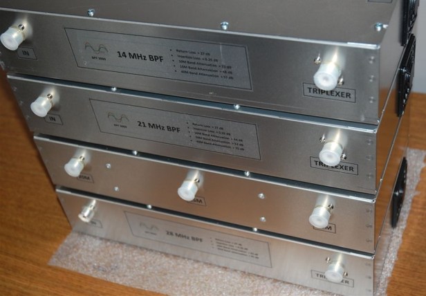
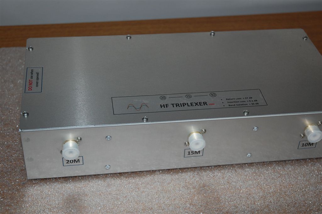
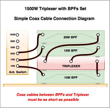
On a photo below, Triplexer box installed between 10 and 15 meter band BPFs and this box order allows to use the shortest coax connection cables.
- Coaxial cables between BPFs and Triplexer must be as short as possible.
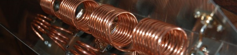
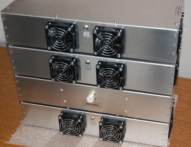
There are two cooling fans installed for each BPF because they are smaller and less powerful (60mm vs 92mm) than those installed on a 3000W set boxes. These cooling fans blow directly toward coils under stress and it woks quite efficiently.
For a 2″ longer box 1444-1773 and the 5th order BPFs three cooling fans can be installed to allow BPFs to be used up to 3000W of output power.
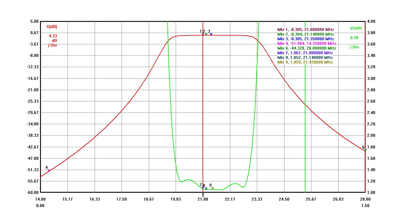
Please, see completed 20M BPF graph below:
- Insertion Loss < 0.25 dB
- Band Isolation ( 15 M > 47 dB, 10 M > 72dB, 40M > 57dB)
- VSWR < 1.05 (Return Loss > 28 dB)
- Expected Band Isolation with Triplexer > 80dB
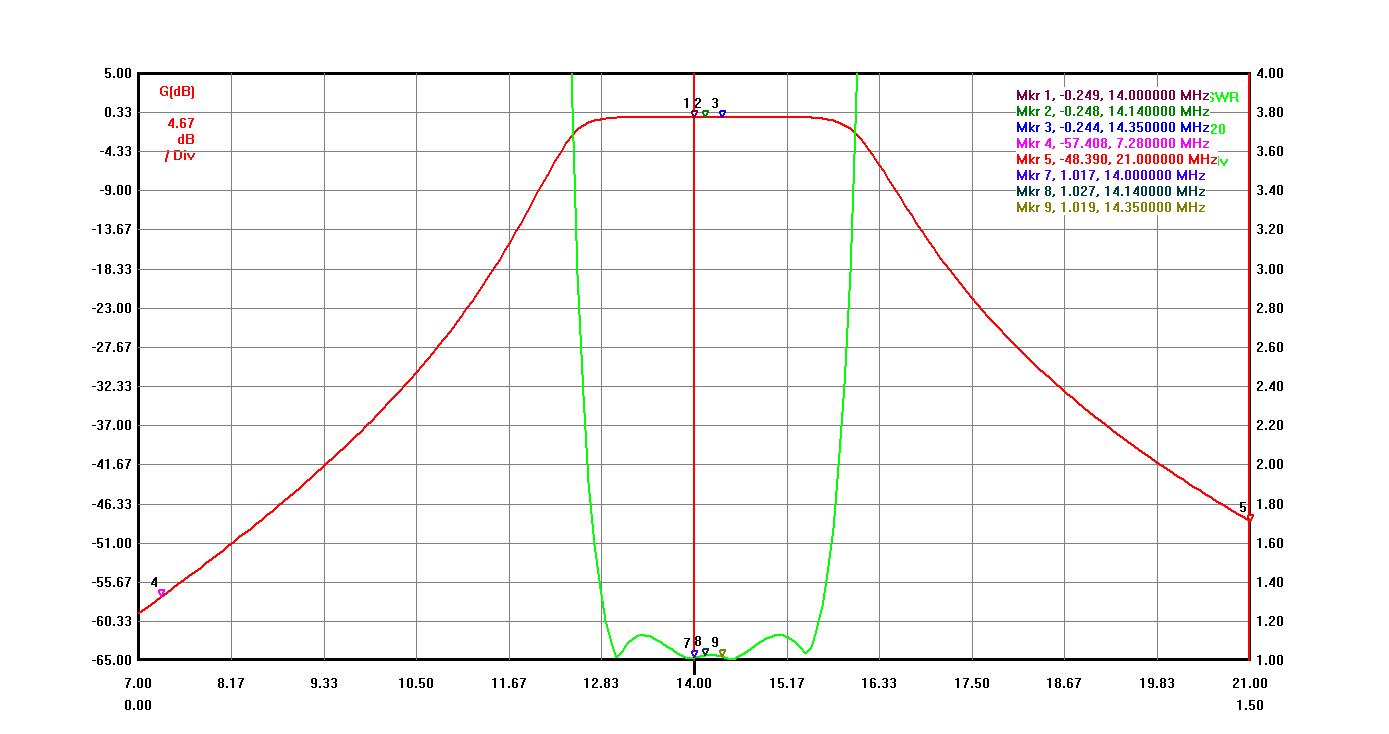
Band isolation can be easily increased to -50dB for 15M band with some different capacitor values. Increased band isolation brings Insertion Loss to a little higher value to -0.27-0.28dB value.
Please, see completed 15M BPF graph below:
- Insertion Loss < 0.32 dB
- Band Isolation ( 20 M > 52 dB, 10 M > 44dB, 40M > 80dB)
- VSWR < 1.07 (Return Loss > 28 dB)
- Expected Band Isolation with Triplexer > 75dB
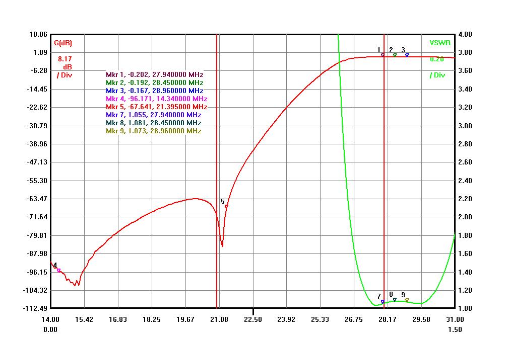
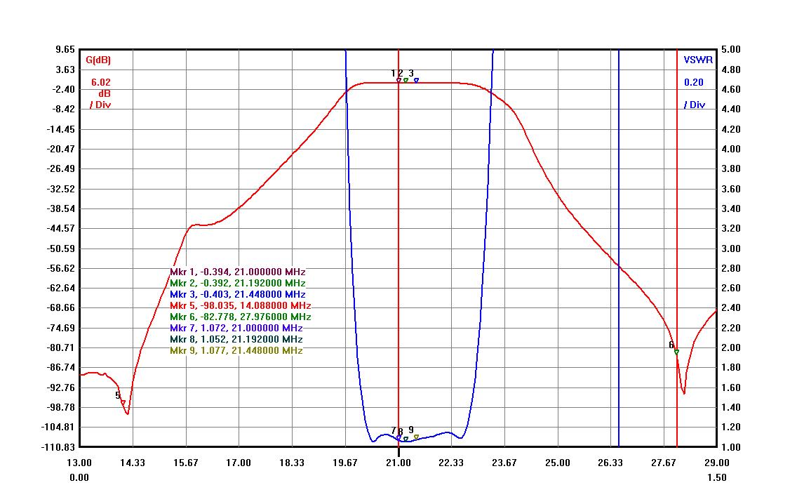
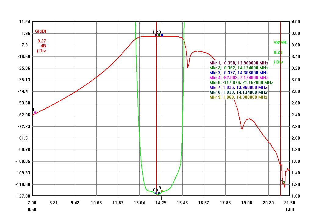
Please, see 10M BPF 3rd order with 15M LC trap added graphs below:
- Insertion Loss < 0.2 dB !!!
- Band Isolation ( 20 M > 90 dB, 15 M > 65dB)
- VSWR < 1.08 (Return Loss > 27 dB)
- Expected Band Isolation with Triplexer > 85dB ( > 120dB for 20M band)
10M band built using the same circuit as for 3000 watt set.
The 10M band requires as much 20M isolation as possible to decrease the 2nd harmonics from 20M band to its minimum level.
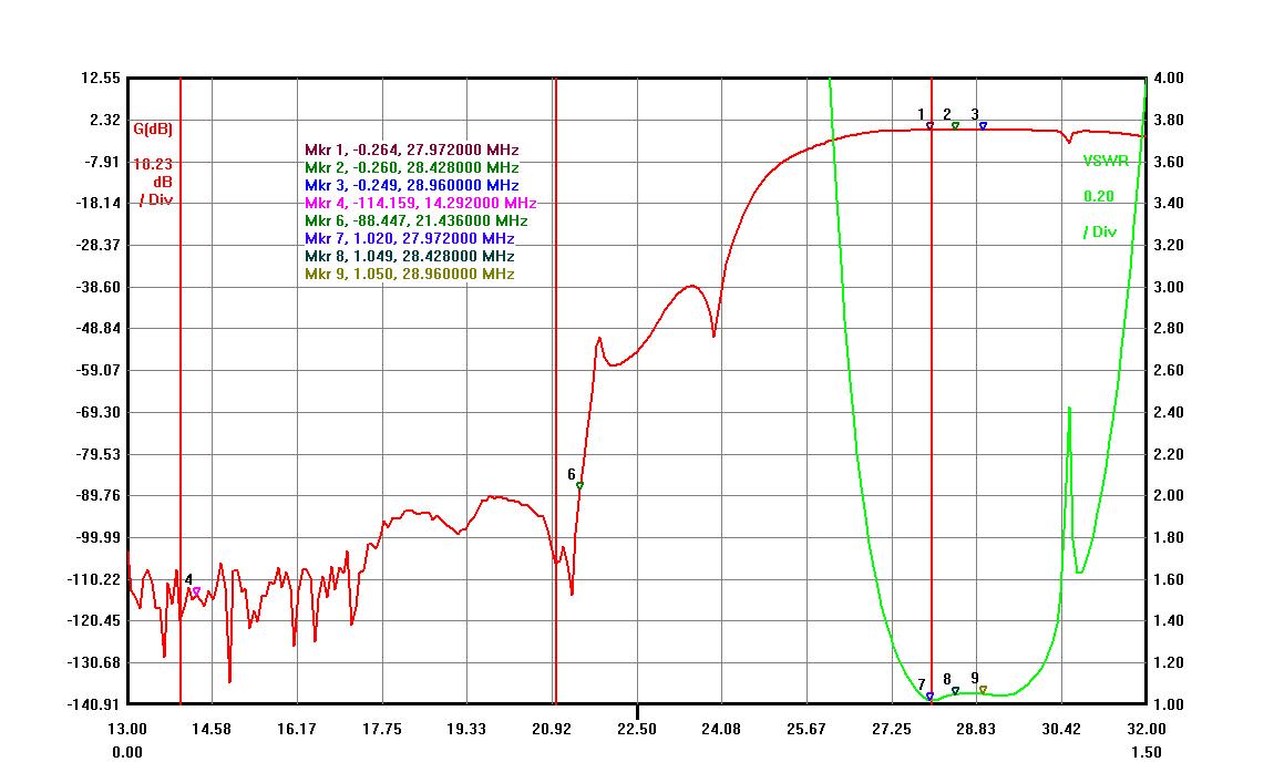
Please, see two graphs below for 10M BPF (Wide and In-Band):
Please, see a Triplexer pictures below. I publish no graphs for the triplexer because they are very close to any triplexer graphs published on this website.
- Insertion Loss < 0.11 dB
- Band Isolation > 30 dB
- VSWR < 1.08 (Return Loss > 27 dB)

10M Band Triplexer with all BPFs attached:
- Insertion Loss < 0.3 dB
- Band Isolation (20 M >120 dB, 15 M > 88dB)
- VSWR < 1.08 (Return Loss > 27 dB)
15M Band Triplexer with BPFs attached:
- Insertion Loss < 0.4 dB
- Band Isolation ( 20 M > 90 dB, 10 M > 75dB)
- VSWR < 1.08 (Return Loss > 27 dB)
20M Band Triplexer with BPFs attached:
- Insertion Loss < 0.32 dB
- Band Isolation ( 15 M > 100 dB, 10 M > 120 dB, 40 M > 60 dB)
- VSWR < 1.08 (Return Loss > 27 dB)
- Triplexer is a balanced filter system and every port must see 50ohm load
- You can build an antenna switch with 50 ohm loads on every band port using KK1L switch PCB (-67dB minimum port isolation)
- You can buy a 2×6 switch with interlocking system from RemoteQTH.com (-71dB minimum port isolation) .
- Some antennas switches can be modified to connect unused antenna ports to 50 ohm resistors.
Connection coax cables between Triplexer and BPFs should be as short as possible for the best matching impedance between boxes.
Here is a simple diagram and filter’s location for this reason.

Hi,
All prices are on For Sale webpage. Shipping to Europe is quite expensive and the shipping for a package of four HP filters can cost 300-350 Canadian dollars.
Pavel
Hello Pavel, a few months ago, I approached you for information about a triplex- I intend to set up a small station contest 2 tribal on the high bands . Can you give me an idea of the price with transport to France for a set for the triplexer with the 3 bpf. I’m running up to acom 1000
Hello Pavel, a few months ago, I approached you for information about a triplex- I intend to set up a small station contest 2 tribal on the high bands . Can you give me an idea of the price with transport to France for a set for the triplexer with the 3 bpf. I’m running up to acom 1000
Hi Pavel,
Thanks for building/supplying the above kit for us. We use it successfully at the ZM4T contest station for well over one year now. It was also used during our WRTC2018 participation (Y89N – ZL4YL/ZL3IO). So it has seen a few places already.
73 Holger, ZL3IO
Hi,
Price is between $1308.00 and $1378.00 based on chosen enclosure and BPF’s order.
For DX-pedition I would go with a smaller 1444 series boxes and without any cooling fans as 1000W is not a problem at all.
I could ship it by the end of January-beginning of February 2019.
73
Pavel
VA6AM
Please advise of price / supply time for the the triplexer with the 3 bpf ‘s.This is for an upcoming dx-ped in March 2019.
We are running up to 3 xAcom 1010 Amps into these filters.
Many Thanks
73 EI5GM