- 2000W Triplexer
- High Power BPFs
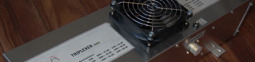
- 3000W Triplexer with BPFs set
- 2000W Triplexer with BPFs set
- VC3S claimed the new MS High Power Canadian record in 2016 CQWW RTTY using VA6AM Triplexer and BPFs. Their short story and 3830 Result.
- NP2N used VA6AM Triplexer with BPFs during 2017 ARRL CW DX contest. Their M/2 category short story and 3830 Result.
- N5DX, VE2IM (1500W set) and 9M6NA used VA6AM Triplexer + BPFs with a great scores in SOHP AB category during 2017 CQWW CW. You can find their results at 3830 Score page.
- CR5E team used a stack of tribanders with a few triplexers and BPFs. This is their good 3830 result with the new filter system in 2018 CQWW SSB.
3000W High Power Triplexer General Specification:
- Insertion Loss < 0.1 dB
- Band Port Isolation > 30 dB (see graphs below)
- Return Loss > 28 dB
CW/SSB Recommended Output Power with antenna VSWR < 1.5
- 3000W CW/SSB to any band port with one signal at a time (SO2R / M2 category)
- 2500W to every band port if all three bands used simultaneously (MM category)
- 1500W no problem to any band port without a cooling fan installed.
- Enclosure is 1411ZU (U-unpainted raw aluminum) from Hammond
- Without Fan – 17 x 5″x 4″ (42.5 x 12.5 x 10 cm)
- With Fan Installed – 17″x 5″x 5″ (42.5 x 12.5 x 12.5 cm)
- 1411Z powder coated enclosure is not suitable as it is painted inside.
- The fan (50 CFM, 12VDC, 92 X 25 mm) installed in the middle of enclosure to equally cool all triplexer sections.
- 2.1mm DC connector installed to power a cooling fan.

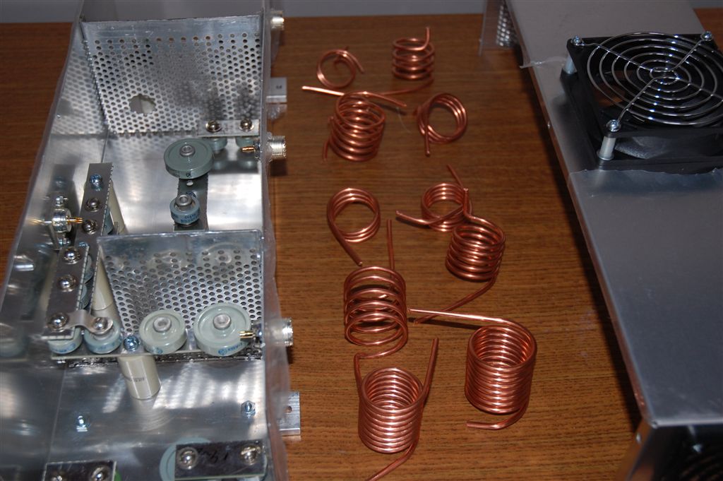
The photo above is a nice Hammond box to use to build a triplexer…but it painted inside. I used it once and spent too much time removing powder coating. That is it! Below is unpainted aluminum enclosure I am using now.

Below is a work-in-progress triplexers with shields between band shown.

- From very beginning, I would like to say that the triplexer band isolation level is not a problem to achieve.
- The most difficult part of building a good triplexer is to tune it to a good Return Loss (or low VSWR) and Low Insertion Loss.
- Triplexer band legs should have Impedance close to 50 Ohms
Please, read more general information about triplexer on Low Power HF Triplexer page.
Triplexer allows to use one tribander as three independent antennas with isolation between bands better than 30dB.
- Other 50-55dB can be added by BPFs and with total isolation around -80 dB or better we can operate a legal power setup. Actually, with -80dB of band isolation 6kW of power is an acceptable level to work with.
As of 2016, there is only one triplexer (combiner) made by 4O3A for a high power application as I known of. I talked to people who have it, I got graphs and numbers of it and it turns out I can try to do better than that.
- Air coil mutual coupling required a very careful consideration in the triplexer layout design.
Cauer(Elliptic) filters I am using are very sensitive to coefficient of coupling. If coupling between coils exists, capacitor values have to be changed to compensate it. Practically, it is a very difficult thing to do.
Coil mutual coupling does exist but with proper orientation, winding direction and distance between coils I got it working.
- Triplexer band layout design was changed to allow aluminum shields installation between bands.
Please, see on a photo below how perforated aluminum shields installed inside the triplexer. The photo is a Triplexer work-in-progress assembling stage.
- It is very important to shield triplexer bands inside the triplexer. Without shields installed, coils “talk to each other” and some isolation lost when a real power applied (up to 6 dB depends on an output power level).
- In 4O3A combiner 10 and 15 meter band coils located very close to each other and it can cause the coupling problems.
- Thanks to those 4O3A combiner users who brings up that problem to encourage me to pay a special attention to this part of design.
- I’ve had a few customers who complained about interference between 10 and 15 meter bands using 4O3A combiner.
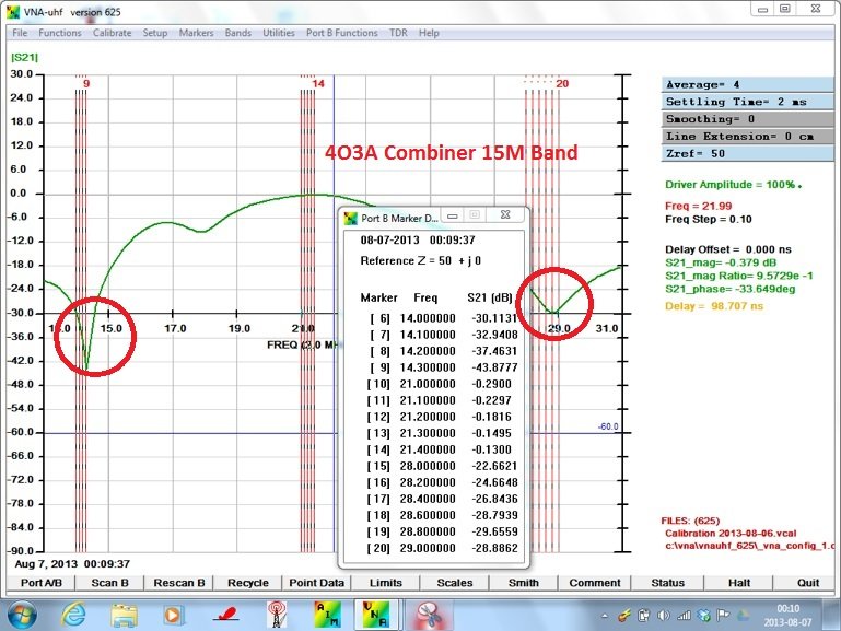
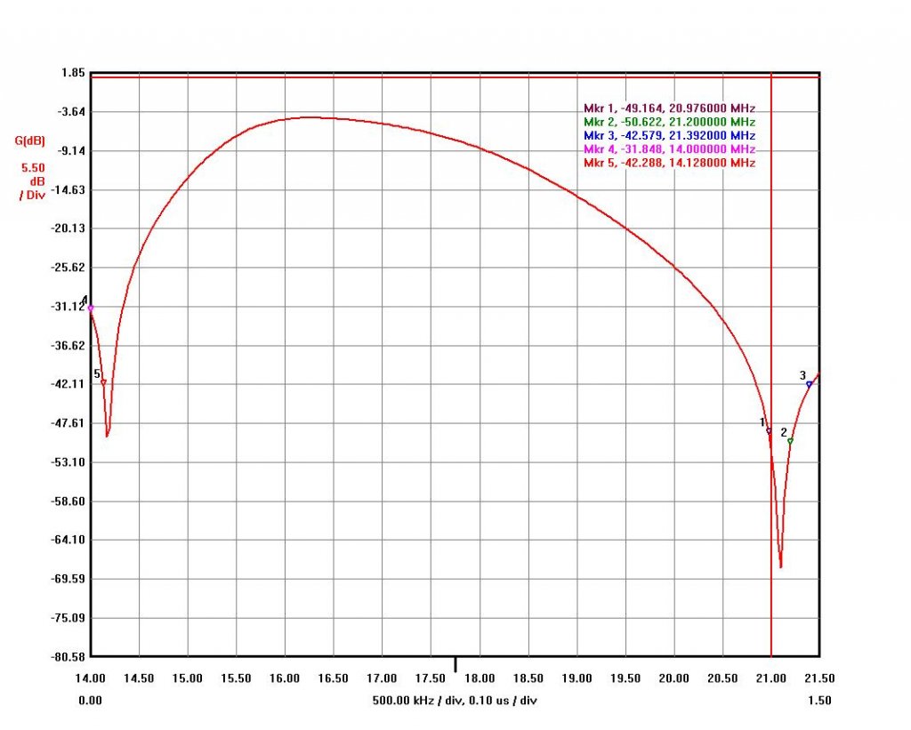
Please, see below graph of 15M band for 4O3A combiner. You can see how sharp LC trap resonance for 20M band and not for 10M band.
From graph below, I can see that coupling problem could exist in 4O3A combiner.
In real life, you can experience interference from 10M band transmission while listening on 15M band (or listening on 10M band while transmitting on 15M band). I found the same behavior during my triplexer testing and solved that problem by changing triplexer band layouts and installing an aluminum shield between bands.
For the comparison table below, some numbers taken from 4O3A website and some from graphs published on this page.
| Band | 20M Radio | 15M Radio | 10M Radio | |||
| Call-Sign | VA6AM | 4O3A | VA6AM | 4O3A | VA6AM | 4O3A |
| Return Loss (dB) | >26 | >20 | >26 | >20 | >26 | >20 |
| Insertion Loss (dB) | <0.1 | <0.1 | <0.1 | <0.22 | <0.1 | <0.1 |
| 20M Isolation (dB) | 0 | 0 | >30 | >30 | >43 | >43 |
| 15M Isolation (dB) | >37 | >35 | 0 | 0 | >35 | >16 |
| 10M Isolation (dB) | >45 | >33 | >30 | >23 | 0 | 0 |
- I think 4O3A triplexer I got graphs from is not perfectly aligned and some numbers could be better but some problems are there. In the table above, 15M band Insertion Loss is 0.22 dB on average and at maximum loss level it is 0.29 dB on the graph.
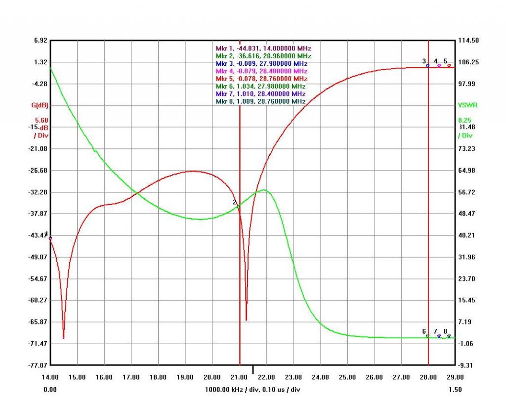
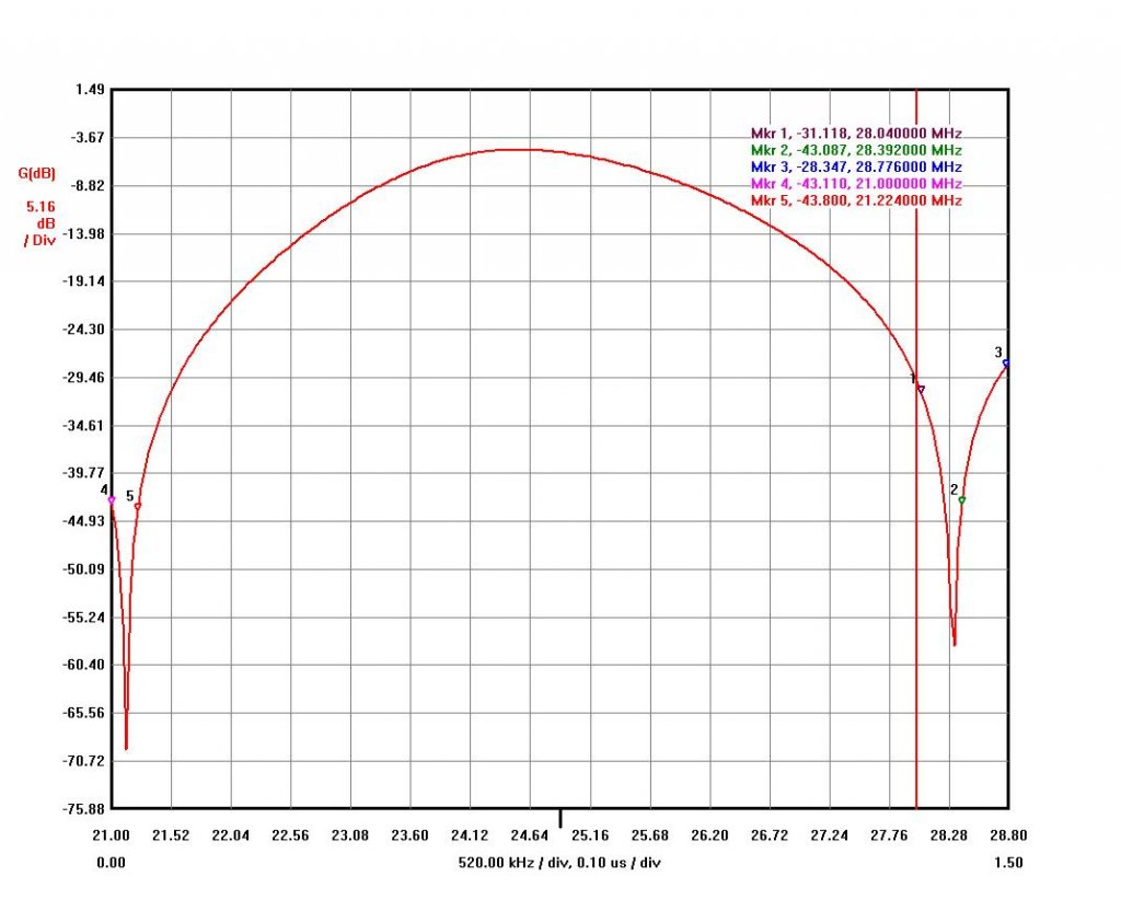
The 15M band 4O3A In-Band Insertion Loss value range is from 0.29 dB to 0.13dB and it is not good anyway. It should be almost a straight line over the band like on my 15M band triplexer In-Band graph shown below.
From the graph above, 4O3A Combiner 15M band minimum attenuation is 16dB only. I think if it would be properly adjusted it could be around 22-23dB. This is a better number but 8 dB lower than 15M band isolation from my design.
Please, see all graphs below.
10M Band graphs below:
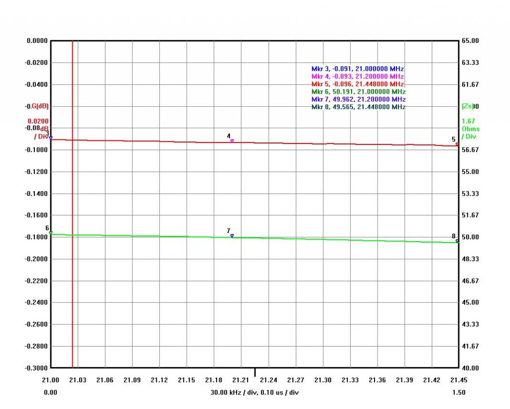
- Insertion Loss < 0.1 dB
- 15M Band Isolation > 37dB
- 20M Band Isolation > 44 dB
- VSWR < 1.07 (Return Loss > 28dB)
- The last is Zs parameter which should be as close to 50 Ohm as possible
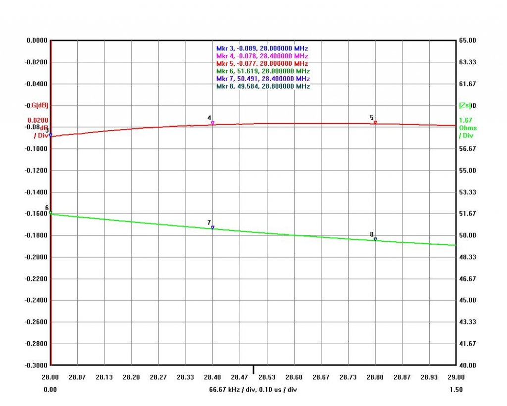
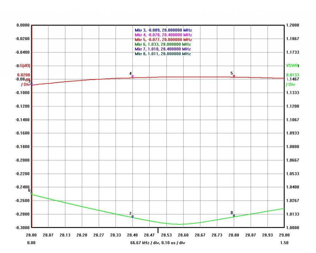
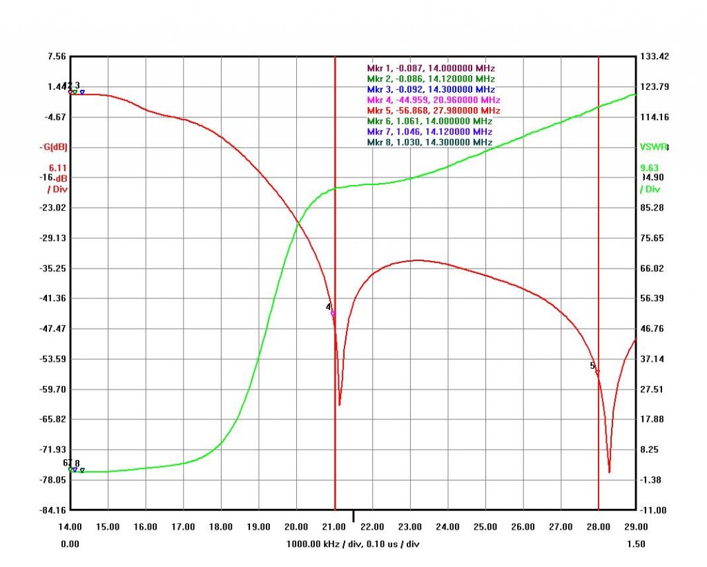
15M Band graphs below:
- Insertion Loss < 0.1 dB
- 10M Band Isolation > 30dB (28.0-28.8 MHz)
- 20M Band Isolation > 30 dB
- VSWR < 1.07 (Return Loss > 28dB)
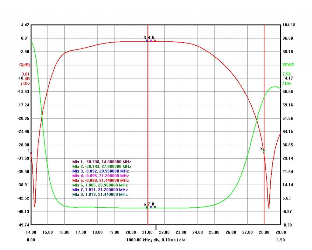
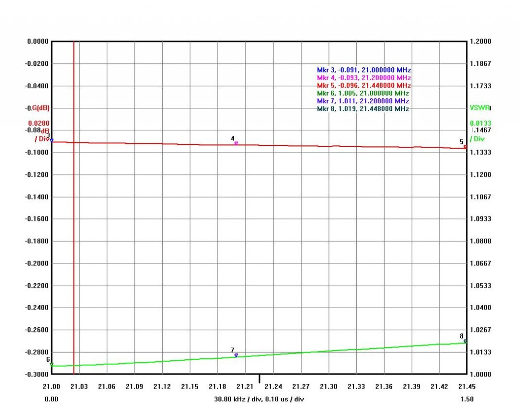
- The last is Zs which should be as close to 50 Ohm as possible
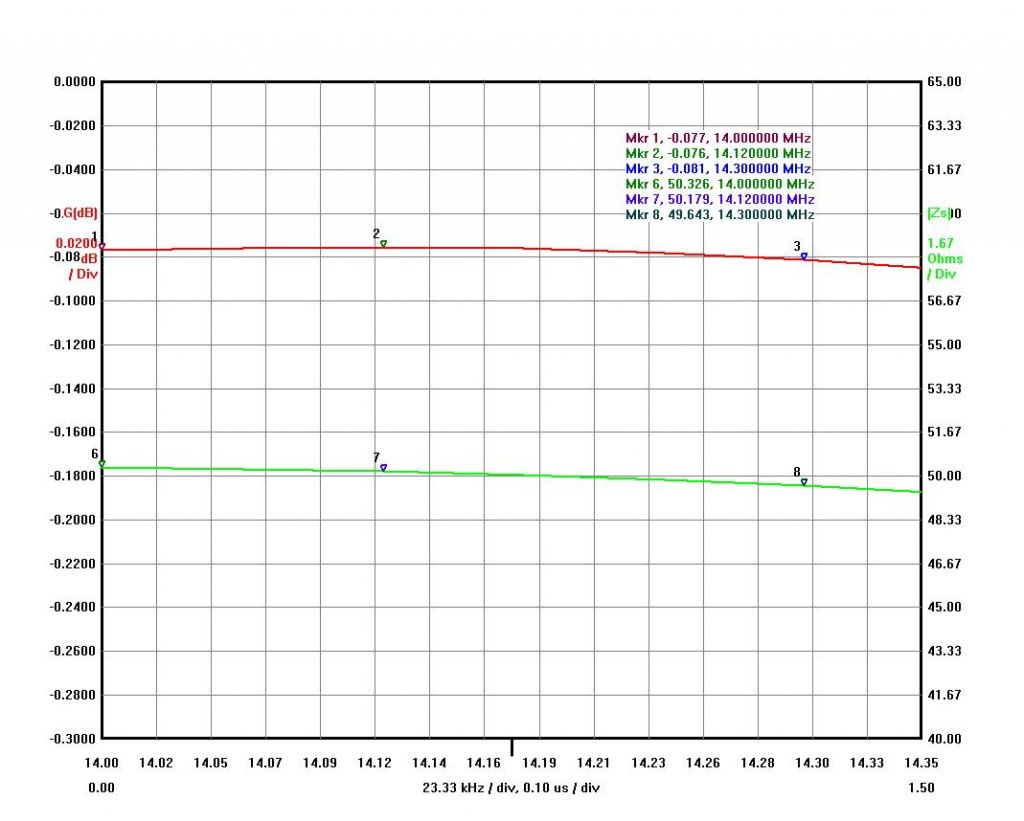
20M Band graphs below:
- Insertion Loss < 0.1 dB
- 10M Band Isolation > 50dB
- 15M Band Isolation > 43 dB
- VSWR < 1.07 (Return Loss > 28dB)
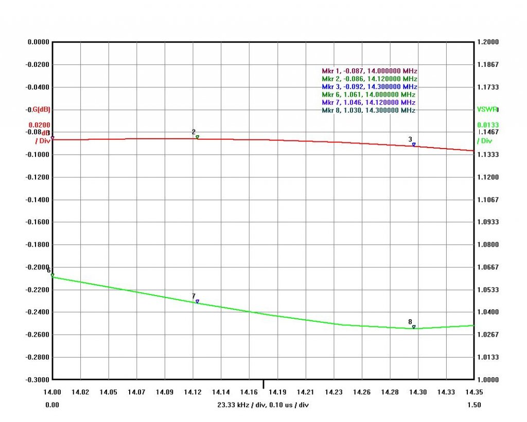
- The last is Zs which should be as close to 50 Ohm as possible
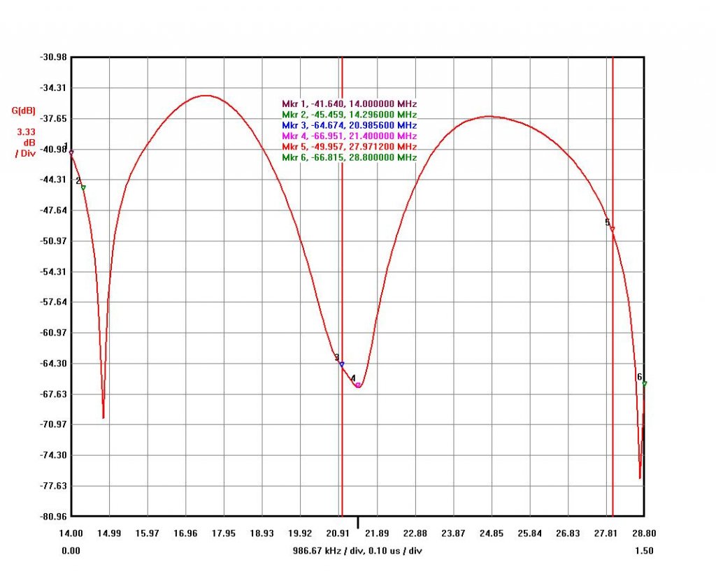
Please, see graphs below of band Isolation made in a different way. It measured by connecting VNA to both bands output ports. It is a band isolation when two radios connected to those bands.
Below is isolation between 20 and 15 meter bands.
Below is isolation between 10 and 15 meter bands.
Below is isolation between 20 and 10 meter bands.
The 15M band isolation is sum of both 20 and 10 meter bands 15M LC traps. The same is for 10 and 20 meter bands as there are many LC traps on that frequencies and each add some attenuation for the measurements…actual numbers are still above -43dB between those bands.
1500 and 3000 watt power smoke test:
First, I tested my prototype Triplexer with 1500 watt power level. The Triplexer Insertion Loss per band is less than 0.1dB or less than 40 watts of power loss for 1500 watts from amplifier. In CW/SSB it is around 25 watts of dissipated heat per a band port.
I tested the Triplexer without air cooling by applying 1500 watt power and found some coils got a little bit warm. Actually, for this power level Triplexer can work without air cooling. Despite the fact, I installed 12VDC 50CFM fan to provide an air flow inside the triplexer.
- The 1500 watt test shows that triplexer design is good at this power level to provide a sufficient level of band isolation.
- The mutual coupling level between bands inside the triplexer is very low at any power level.
LTSpice software simulation shows that the triplexer can handle power up to 4000 watts based on a military doorknob capacitor nominal reactive power(KVar). Capacitor maximum power level could be twice higher than that stated as a normal KVar (no specification found for a maximum power).
I would like to thank Gordon, VE6SV who let me test my high power set of Triplexer + BPFs at his station. The testing with 3000 watt was done during a Canada Day contest.
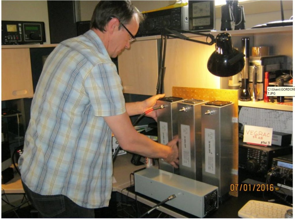
In short, Triplexer is good for 3000 watt power level, no issue, no overheating at all. I think it can be used with even more output power but I’ve never tested it as I do not have amplifier that level.
- Based on my power tests and LTSpice software simulation, I can recommend to apply < 2000 watts to every band port if all three bands used simultaneously (MM contest category).
- If two amplifiers transmit the same time, < 2500 watt can be applied to every band port(M2 category).
- If a single port used at a time (SO2R or MS category style), < 3000 watts of power no problem.
- A few HAMs used VA6AM Triplexer and BPFs with OM3500 power amplifier and this is the best “smoke test” in a real contest environment!
