Band-pass filters are items to have on each station which is in SO2R category or any Multi-Operator category ( M/S, M/2, M/M). Filters help to minimize harmonics to allow a few bands simultaneous operation.
This webpage dedicated to Low Power band-pass filters. 10 and 160 meter BPFs are a Chebyshev type (160M is a classic W3NQN design). 15, 20, 40 and 80 meter BPFs are Cauer type filters.
Please, see in a table below with some numbers for LP filters.
BAND |
Insertion Loss (dB) |
Return Loss (dB) |
UPPER Band (dB) |
DOWN Band (dB) |
| 160 | < 0.27 | > 25 | > 45 | >40 (1MHz) |
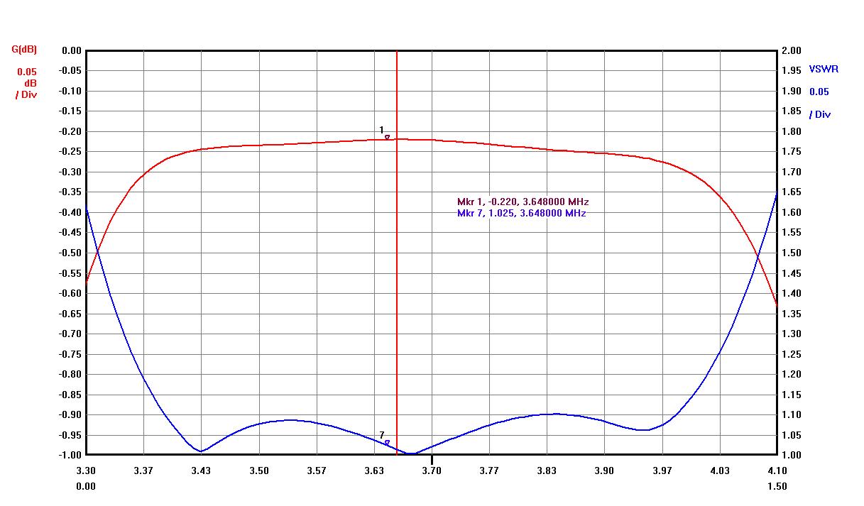
| 80 | < 0.25 | > 25 | > 65 | > 55 |
| 40 | < 0.25 | > 25 | > 70 | > 60 |
| 20 | < 0.25 | > 25 | > 60 | > 60 |
| 15 | < 0.3 | > 25 | > 55 | > 50 |
| 10 | < 0.31 | > 25 | >27 (50MHz) | > 40 |
Table below shows the difference between popular W3NQN (5B4AGN filters are W3NQN design) and Cauer type BPFs for adjacent bands (minimum values).
All parameters for Caue r(Elliptic filters) design are better compared to W3NQN design.
BAND |
W3NQN (dB) |
Cauer (dB) |
Difference (dB) |
| 80 | > – 42 | > – 55 | 13 |
| 40 | > – 46 | > – 60 | 14 |
| 20 | > – 37 | > – 60 | 23 |
| 15 | > – 34 | > – 50 | 16 |
| 10 | > – 25 | > – 40 | 15 |
- Cauer (Elliptic) filter type is a better option compare to Chebyshev type for a higher adjacent band attenuation but they have lower attenuation for a nonadjacent bands
Graph below shows the difference between Cauer(Elliptic) and Chebyshev type 20M filters. Cauer is on a left and Chebyshev is on a right side. You can see 15- 20dB difference for adjacent bands in favor of a Cauer type filter calculated by a filter software.
Please, click on a graph for a larger view.

Band-pass filter boards is to use a regular radial ceramic capacitor (3kV or 6 kV) or to use custom made MICA capacitors from Charcroft. I used those Charcroft capacitors before with a success but the production lead time is up to 3-4 weeks and some other capacitor types was considered as a replacement.
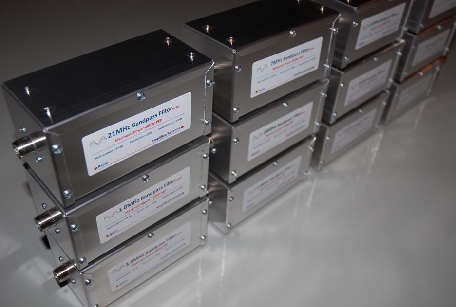
BPF boards are to fit into Hammond 1411MU enclosure. Hammond makes it with only four holes for the box cover (two on each side). It looks much better with three more added on each side of the box
Filters designed with trifilar type winding to decrease the potential maximum voltage applied to capacitors and as a result a better capacitor reliability. You can see a simple math of a trifilar coil transformation on the 20M LP BPF webpage.
- As always, the goal was not to achieve the maximum possible band attenuation but to find a balance between good band isolation and low Insertion loss. Low insertion Loss means a long life of the filter unit.
Return Loss (VSWR) should be an easy to achieve parameter as well. -50-60dB of band attenuation is a good result which should meet a filter requirements for many different applications, especially together with Triplexer.
The filter Insertion Loss is a very important parameter to keep it low to reduce the heat dissipation and as a result a better filter reliability. Low Insertion Loss mostly defined by Q-factor of coils and a proper coil design should be made.
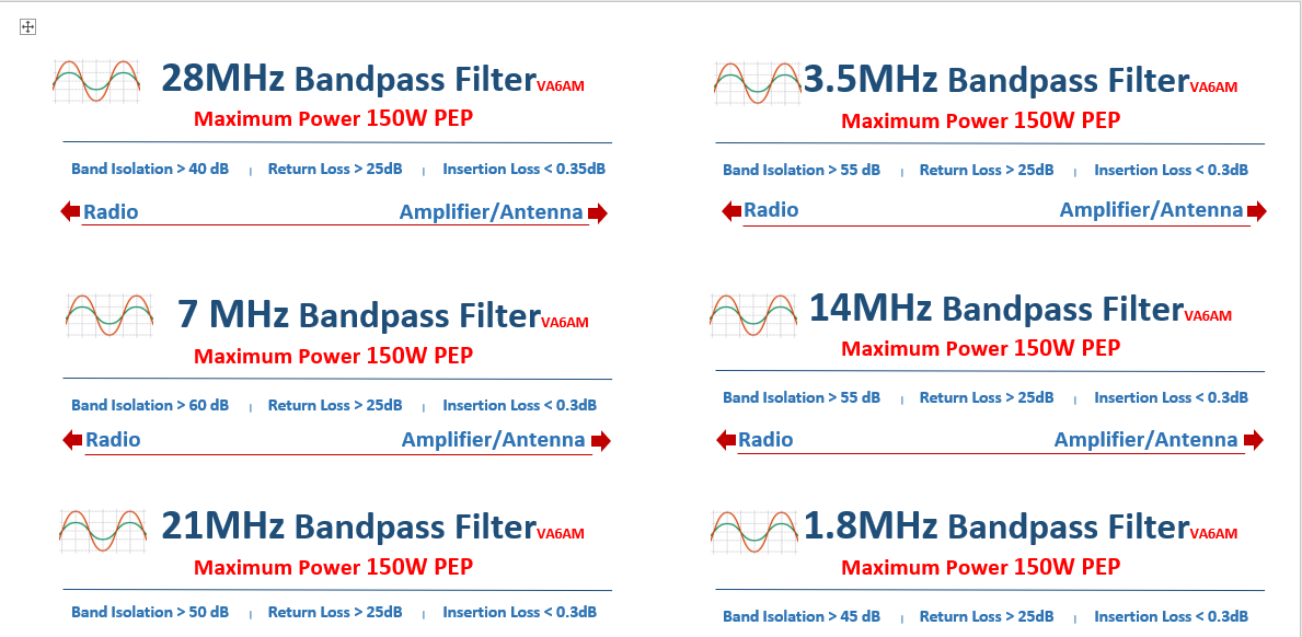
LP Band-pass Filter box enclosure is: 6″ X 3″ x 3″ ( 7″ long with connectors”):
- 15, 20, 40, 80 band BPFs are Cauer type, 10 and 160 band BPFs are Chebyshev type.

10M BPF can be built as a Cauer type for a better 15M band attenuation but drawback of that filter type is a lower attenuation of 2th harmonics from 20M band. The Chebyshev type I used has close to -80-90dB 20M band isolation.
- The most efficient way to minimize the TX (transmission) harmonics is to install filter on a transmitting radio. It means if you have harmonics interference from 40M TX to 20M RX, the first thing to try is to install 40M BPF on a 40M TX radio.
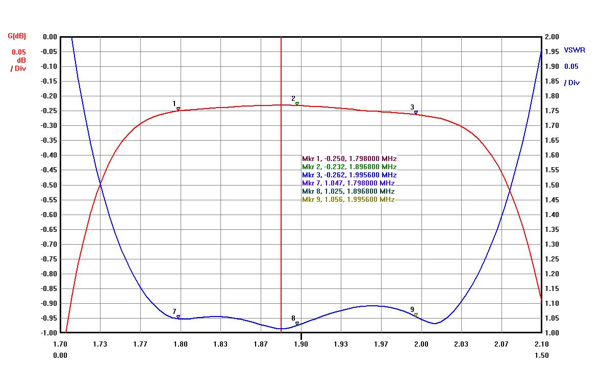
160M BPF:
It is the 3rd order classic Chebyshev type band-pass filter.
You can find 160M BPF data in the article W3NQN_May_June_1998_QST but I recalculated the 160M BPF to be used with T130-2 toroid type and not T130-6 as it is in the original W3NQN design. Results are almost identical with a tiny difference for an Insertion Loss in favor of type 2 toroids.
- Return Loss > 26dB (VSWR < 1.1)
- Insertion Loss < -0.25dB
- 80M Isolation > -45dB
- 40M Isolation > -65dB

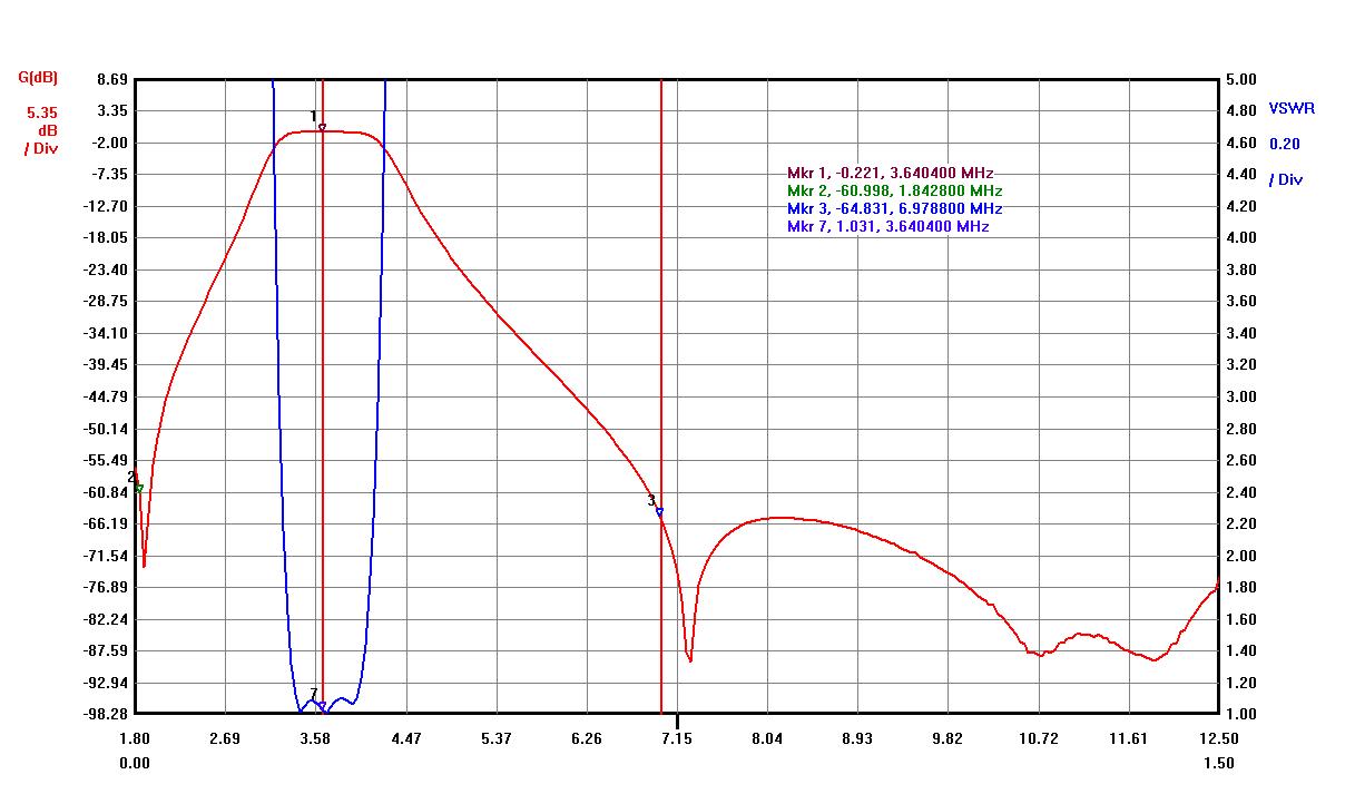
80M BPF:
It is the 3rd order Cauer (Elliptic) type band-pass filter.
- Return Loss > 26dB (VSWR < 1.1)
- Insertion Loss < -0.25dB
- 160M Isolation > -56dB
- 40M Isolation > -65dB (the 2nd harmonics)
- 20M Isolation > -55dB
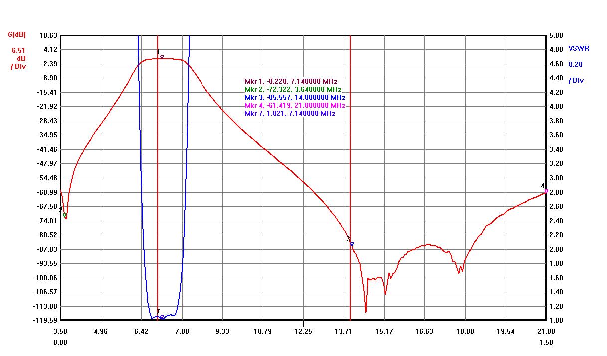
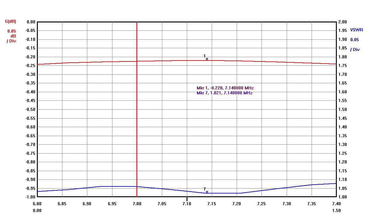
40M BPF:
It is the 3rd order Cauer (Elliptic) type band-pass filter.
A very good 20M isolation to eliminate the 2nd harmonics interference with the 20M band.
- Return Loss > 26dB (VSWR < 1.1)
- Insertion Loss < -0.25dB
- 80M Isolation > -60dB
- 20M Isolation > -80dB (the 2nd harmonics)
- 15M Isolation > -58dB (the 3nd harmonics)
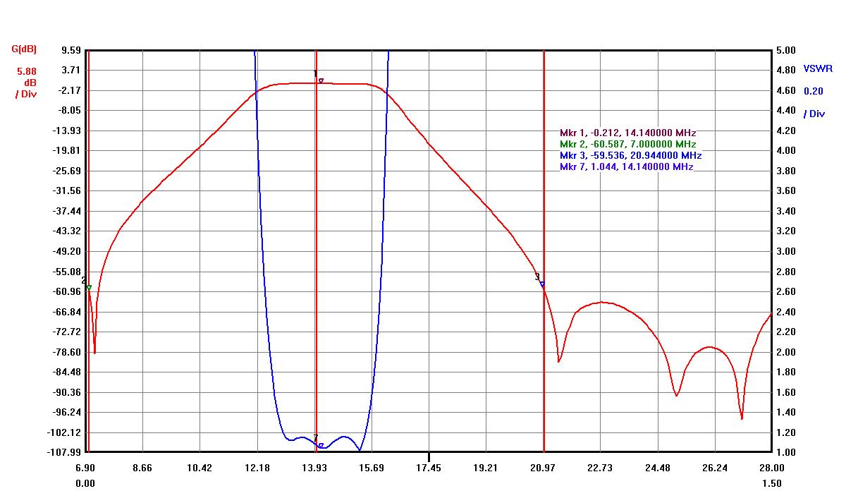
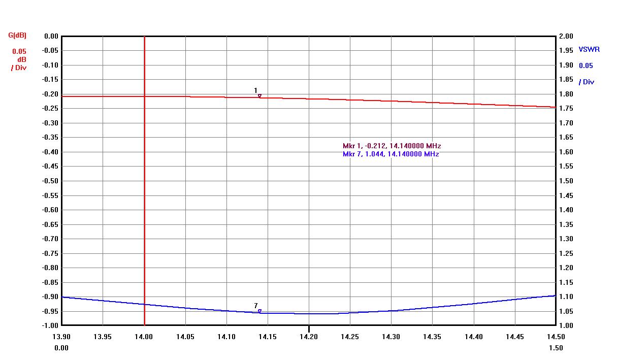
20M BPF:
It is the 3rd order Cauer (Elliptic) type band-pass filter.
I already published 20M band Cauer type BPF on this page but this is a result with new PCB board design and some improved filter model.
- Return Loss > 26dB (VSWR < 1.1)
- Insertion Loss < -0.25dB
- 40M Isolation > -60dB
- 15M Isolation > -60dB
- 10M Isolation >-60dB (the 2nd harmonics)
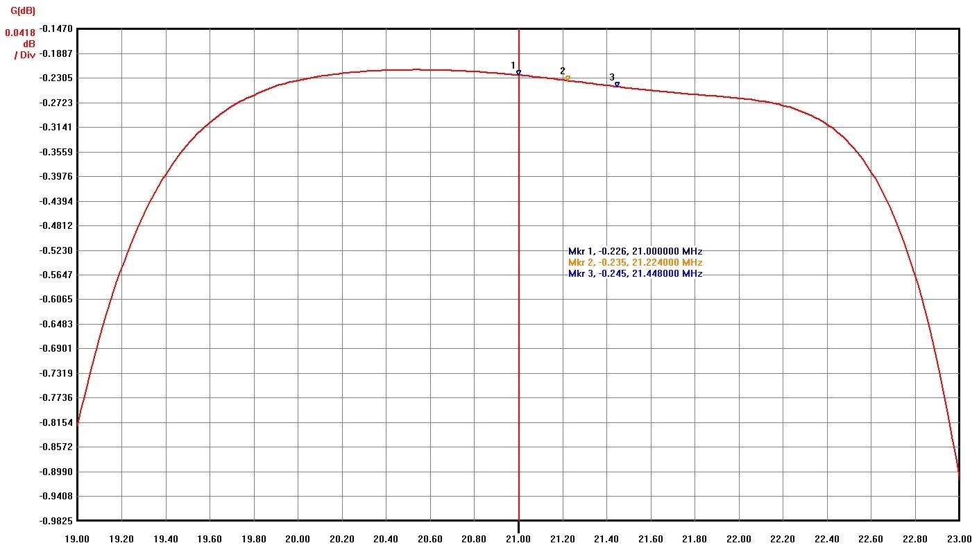
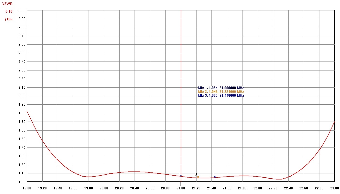
15M BPF:
- The original design changed in favor of lower Insertion Loss and better Return Loss.
- K9YC published an interesting article: BandpassFilterSurvey, where all 15M BPFs have IL more than -0.6dB. As a result those filters for 15M band is overheated and eventually many experienced a capacitor failure.
- My approach here is to decrease that high loss with a little lower band isolation (-50dB is still a good number for 100W output power)
It is the 3rd order Cauer (Elliptic) type band-pass filter.
- Return Loss > 26dB (VSWR < 1.1)
- Insertion Loss < -0.3dB (was -0.43dB)
- 20M Isolation > -50dB
- 10M Isolation > -54dB
Cauer (Elliptic) type 15M BPF has lower 7MHz attenuation (around -35dB) what is typical for 3rd order Cauer type filter. The most efficient way to eliminate harmonics is to install a good filter on a transmission radio, in this case on 40M band (Cauer 40M BPF published on this page has around -55-60dB of attenuation for 15M band).
- Please, remember if 15 and 40 meter antennas installed too close to each other, a direct coupling between antennas can be an issue and no filters can help.

10M BPF:
It is the 3rd order Chebyshev type band-pass filter tuned for contest frequencies up to 29MHz. It build with all air coils and as a result Insertion Loss lower compare to toroid usage.
I already published more detais of 10M band BPF on this page
- Return Loss > 27dB (VSWR < 1.1)
- Insertion Loss < -0.3dB
- 20M Isolation > -85dB
- 15M Isolation > -40dB


Cauer type filters are not symmetrical and on a BPF label the recommended Radio and Antenna connections shown.