160M HP filter comparison (websites can be opened by links):
| Insertion Loss | 80M Isolation | 40M Isolation | |
| VA6AM BPF | < 0.17 dB | > 56 dB | > 100dB |
| VA6AM LPF | < 0.11 dB | > 67 dB | > 84 dB |
- 160M BPF can be designed with a higher number for 80M isolation with Insertion Loss close to -0.2dB.
Recommended BPF Power with antenna VSWR <1.5:
- 3000W CW/SSB (2500W RTTY)
- Without fan installed – 1500W
Enclosure is Hammond 1444-33 :
- Without Fan – 17 x 10″x 4″ (42.5 x 25 x 12.5 cm)
- With Fan Installed – 18″x 10″x 4″ (46 x 25 x 12.5 cm)
In general, schematics is the 4th order Chebyshev inductor-coupled BPF.
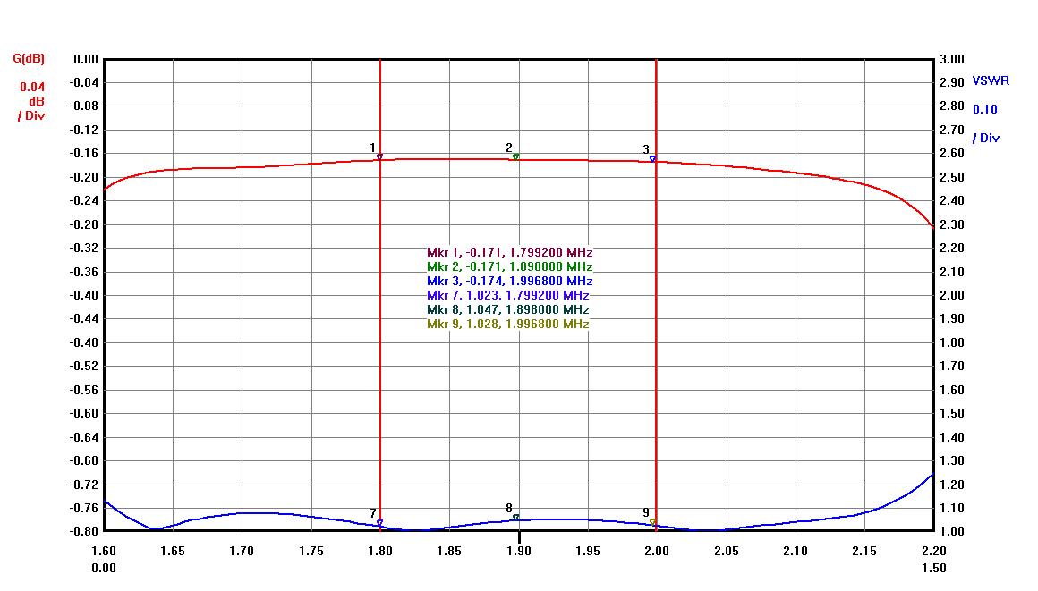
- Insertion Loss < 0.17 dB
- Band Isolation ( 80M > 56dB, 40M > 100dB)
- VSWR < 1.1 (RL > 26 dB)
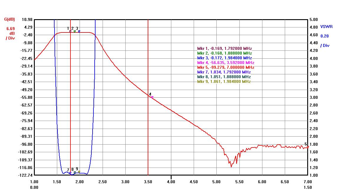
Please, see a wide 160M BPF graph below.
Below is 160M BPF In-Band graph showing IL and VSWR.
The particular 160M BPF built using T200-2 Iron Powder cores as coupling coils. For output power above 2000W coupling coils should be made as a regular air coils.
All capacitors used are very large doorknob capacitors, three in parallel and can withstand output amplifier power up to 10kW without any problems. Each capacitor rated at least of 30KVar of reactive power. Those capacitors was used because no smaller size doorknob capacitors available. It makes filter very reliable but more expensive the same time.
- 160M BPF and not 160M LPF should be used to reduce the broadcast AM local stations signals if any below 1.8MHz interfere with the receiver, especially with SDR radios.
160M BPF has attenuation for low frequencies:
- -21dB attenuation for 1MHZ
- -30dB for 800KHz
- -40dB for 500KHz
If this attenuation level is not a sufficient number some receiver side BPF or HPF can be added.
