The Quadplexer for 4-Band antennas (10-15-20-40 meter bands) can be done inside one enclosure but there is a few drawbacks of such a design:
- It is very difficult to achieve the maximum band Isolation because all bands are harmonics bands. The most difficult to deal with harmonics band combinations are: 20M-10M, 40M-15M and 40M-20M. It could be some coils coupling between those bands inside the enclosure and harmonics will “leak” between bands and no external BPFs can help with such a problem.
- It is hard to locate all band sections inside one enclosure and the whole design in one box will be many trade offs between good parameters and limited band layout options.
- As a result of all tight located bands in one box, band isolation will be lower, the same for Return Loss (VSWR will be a larger number) and Insertion Loss will be not at the minimum point.
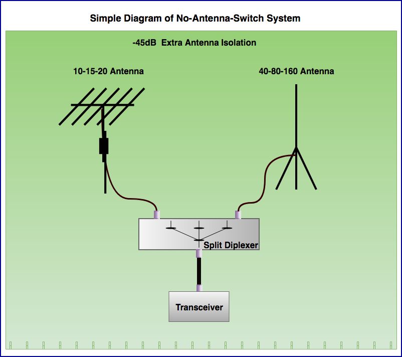
Some other way to achieve the best possible parameters was taken. The so-called Split Diplexer designed to split low and high bands. Antenna input divided into 10-15-20 and 40-80-160 meter band frequency ranges.
4-band multi-band Yagi is quite a popular antenna to be used with such a filter system but some simple 5-or-6-band wire or vertical antenna for Field Day can be connected to the 6 band filtering system to accommodate three or four radios the same time.
The Diplexer schematics is more complex than that of 40-80 meter band Diplexer published here. It is not 3rd order but 5th order design with extra LC traps added to increase all band isolation.
- The main goal of the design was a very low Insertion Loss and wide frequency range with good Return Loss (good VSWR) for all bands.
The simple diagram below shows the whole idea of the design.

- Diplexer splits Antenna input into two frequency areas, below 10MHz and above 10MHz.
- This approach with the added 40 meter BPF or 40-80 Diplexer or 40-80-160 Triplexer allows to use 4, 5 or 6-Band antennas.
- Every box can be designed and built at its maximum performance and contribute the best parameters to the filter system.
Another usage of the Split Diplexer can be a No-Antenna-Switch antenna connection, shown below. All six bands available to the radio and no any antenna switch required. This approach can be useful if:
- a long coax cables to antennas required
- if you would like to increase antenna isolation.
- only a single coax cable available
This diagram shown below is not for SO2R or Multi-Op stations because you cannot operate a few bands simultaneously.
- The photo below shows HP Split Diplexer Work-In-Progress stage where you can see an aluminum shield installed between band ports to maximize the port isolation.

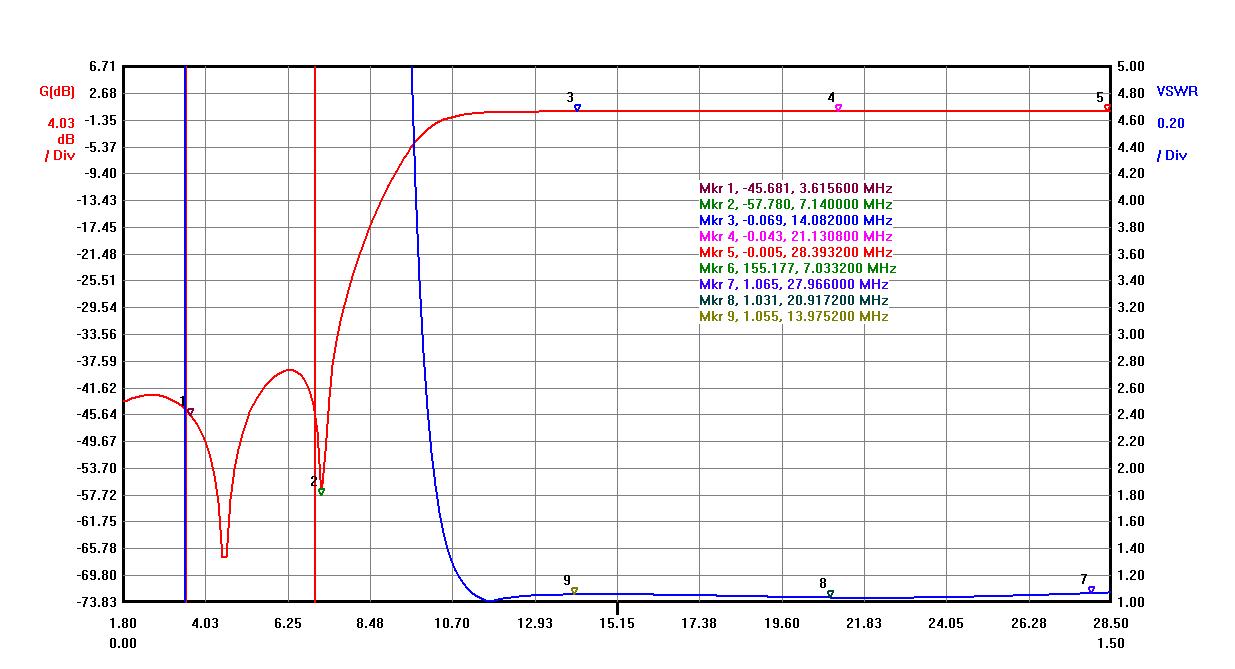
Below is the graph of the Split Diplexer which is LPF (Low Pass Filter) below 10MHz. Two LC traps added to increase attenuation for upper bands.
- Insertion Loss < -0.055dB
- Upper Band Attenuation > – 50dB
- VSWR < 1.1
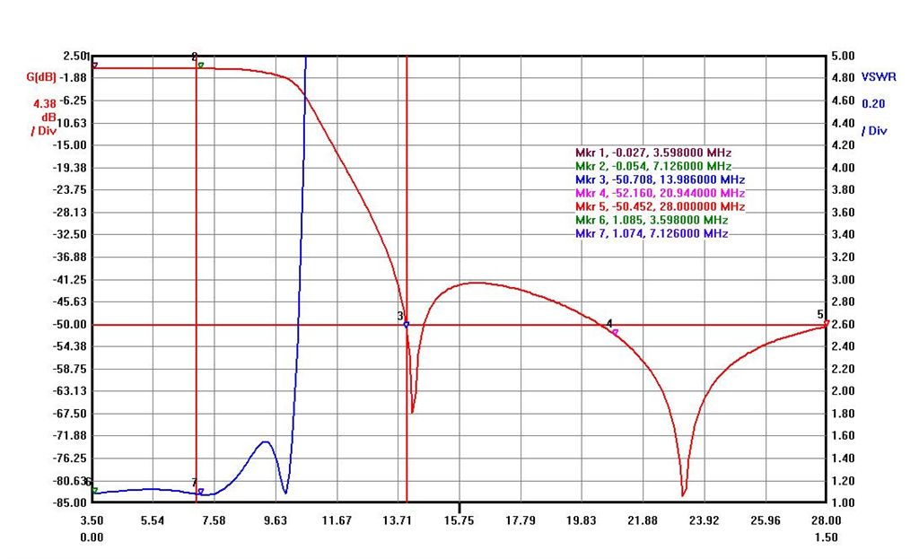
Below is the graph of the Split Diplexer HPF (High Pass Filter) section above 10MHz. Two LC traps added to increase attenuation of low bands.
The important part for this Diplexer HPF section is to have minimum Insertion Loss for 20, 15 and 10 Meter bands as all 10-15-20 meter band goes through the Split Diplexer. These are all numbers:
- 20M Insertion Loss: < – 0.055dB
- 15M Insertion Loss: < – 0.028dB
- 10M Insertion Loss: < – 0.005dB
The same important requirements is to have a wide low VSWR for all 14 to 29 MHz frequency range. On the graph above VSWR is below 1.1 (Return Loss better than -28dB) for the entire three band frequency range.
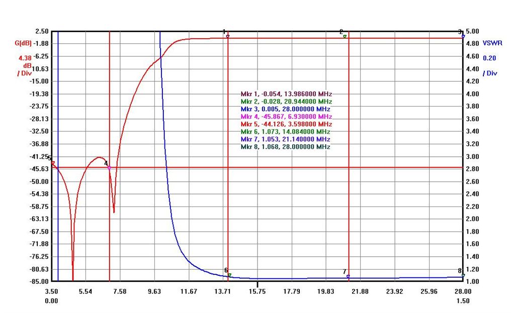
- 40M Band Attenuation > – 45dB
- VSWR < 1.1
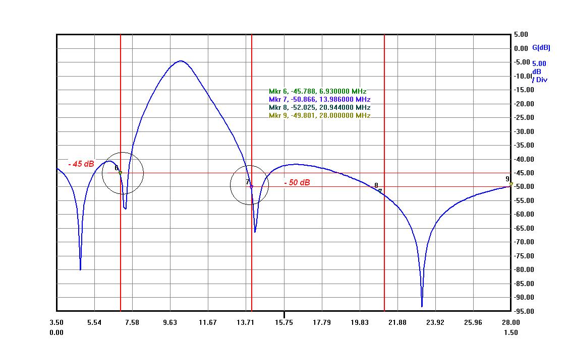
Below is a graph showing band Isolations measured from both band ports with Antenna port loaded to 50 Ohm. The same if two radios connected to the Diplexer.
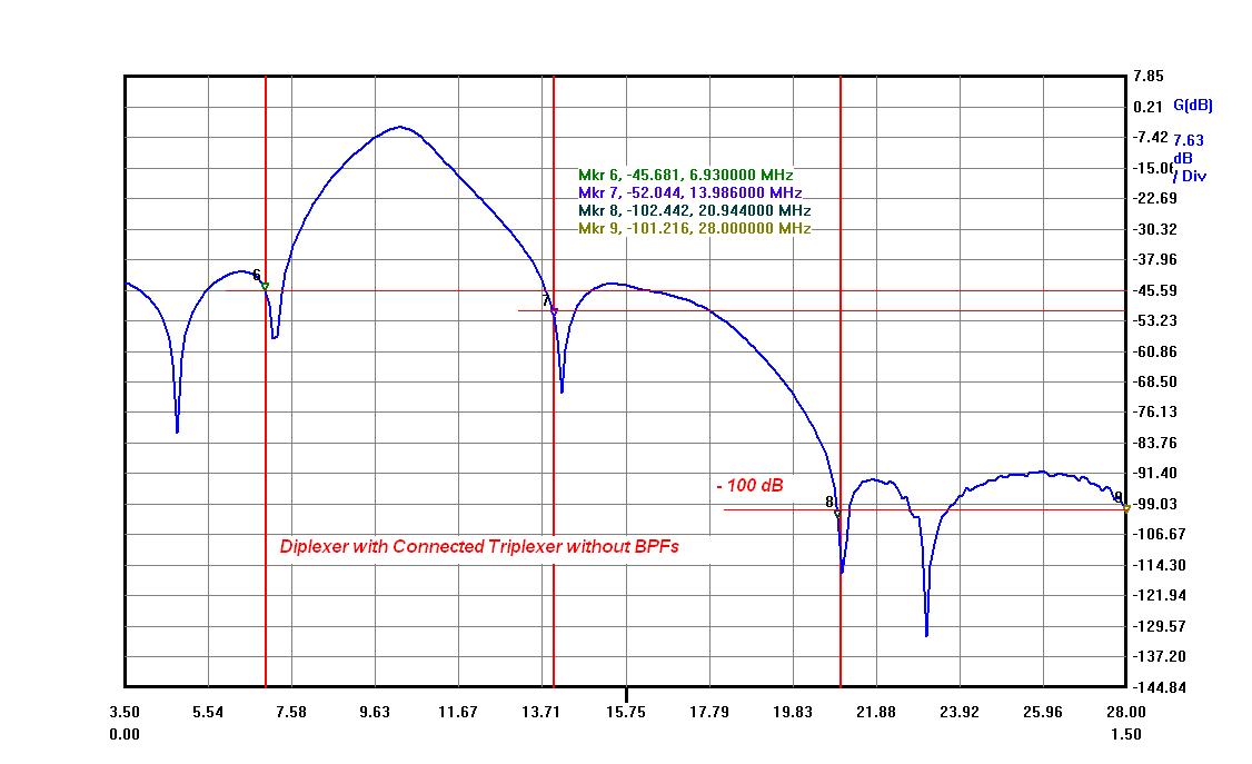
Please, see below the same graph with Triplexer connected (No BPFs connected).
- It was measured the same way as the graph above with VNA ports connected to 20 meter band port (Triplexer) and 40 meter band (Diplexer) ports with all other ports loaded to 50 Ohm.
- You can see the same Isolation level between 20 and 40 meter bands (because Triplexer 20M leg is HPF and there is no 40M attenuation added), but 15 and 10 meter bands isolation is already below -100dB (no BPFs connected)
- -67dB can be added by 20M HP BPF to -45dB delivered by Split Diplexer with a total isolation of 40M band better than -112dB.
- 40M Split Diplexer leg delivers -50dB of isolation for 20M band plus at least -70-82dB (please, read 40M BPF webpage) delivered by HP 40M BPF with a total number better than -120-132dB of isolation.
This a feedback I received from Les, VE3NNT who used his FlexRadio for the test:
“I’m using the OptiBeam OB17-4, 17 elements: 3 on 40m, 4 or 20m, 4 on 15 m and 6 on 10m. The 40m and 20m driven elements are separated by 1.6m.
I did a few quick measurements to give you an idea of the harmonic issue. Transmitting on 40m with 1.5 kw, I can listen to and decode an S5 signal on 20m when the harmonic from 40m is about 15 kHz away. I can listen to and decode an S7 signal on 20m when the harmonic from 40m is about 5 kHz away. The harmonic seems to spread about plus or minus 5 kHz from its center. The overall noise floor on 20m across the band seems to go up about 10 dB from -120 dBm to -110 dBm with a few small deviations across the band. At 100w, I can listen to and decode an S5 signal 2 kHz away from the harmonic.”
Low Power 6-band system built as well. This is 10-15-20 band Triplexer, 40-80-160 band Triplexer and Split Diplexer between them.
- System can be used with 4-, 5- and 6- band antennas. If this 6 band antenna filter system connected to 4-band or 5-band antenna, unused band ports recommended to be terminated with 50 Ohm loads for the best performance. Any standard 1-2 watt loads will work without problems.
Please, see a photo of those units under the test.
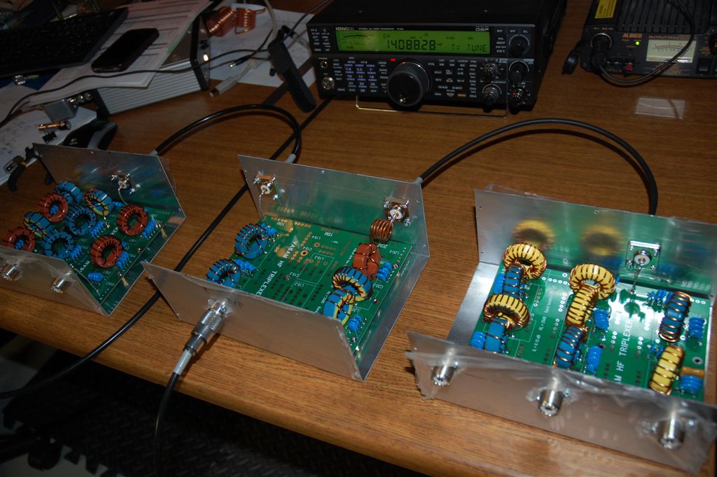
Split Diplexer build on the Triplexer board using LPF and HPF sections and on the photo above Split Diplexer located between low and high band Triplexers.
Multiband antenna connected to a Split Diplexer antenna port and after Low and High band Triplexers the system has 6 band output ports which can be connected to BPFs or an antenna switch (based on a station setup).
The Low Power Split Diplexer graphs shown below:
- Insertion Loss < -0.07dB
- Band Attenuation > – 45dB
- VSWR < 1.1