
I completed low band 40, 80 and 160 High Power filters in a new smaller enclosure Hammond 1444-1773 (17″ x 7″ x 3″). This enclosure is only 3″ or 7.6cm of height.
It is the same DX-pedition style enclosure I used for 1500W Triplexer with BPFs set but 2″ (5cm) longer because I built them as the 5th order BPF with Isolation better than -60dB.
- 40 and 80 meter BPFs are the 5th order Chebyshev type
- 160 meter filter is the 7th order Chebyshev type LPF
- 1500W PEP without air cooling
- 2500W PEP with cooling fans installed
- Three 60mm cooling fans can be installed for an efficient cooling the BPFs.

Below is a photo of how cooling fans installed.
Each cooling fan blows air directly to the coils which are under the highest current stress to make the small fan cooling jobs quite efficient.

This was quite a challenge to find a solution between required high Q coil factors which requires a large in size coils and a smaller 3″ tall enclosure.
Some coils made using Iron Powder cores T200-2 to solve the problem. My concern was how those toroids would behave when at least 1500 watt of output power applied.
I use those toroids where no high current expected. Those are all coupling coils in a filter circuits.
- Up to 2000W there is no any problems to use large toroids as a coupling inductors in my filters. Toroids provide some benefits to the design to improve some numbers, like a band isolation.
Please, see some graphs below:
- 40M band with a re-calculated larger by value capacitors allowed me to build BPF with a regular made of copper wire but smaller in diameter coils compare it with a 3000W 40M BPF version in 1411ZU Hammond box. Please, see a photo below.
This BPF is good for up to 3500W if a sufficient air cooling provided. This particular one was built without fans installed and tested with 1500 watt amplifier without any problems.
- 40M BPF can be built using large Iron Powder cores in the same enclosure. The maximum power will be 2000W and not 3500W as it is with air coils.
Capacitors which you can see on a photo is a large 55mm in diameter doorknob capacitors in parallel, 20KVar of a reactive power each. They will survive 10kW of output power without any problem.

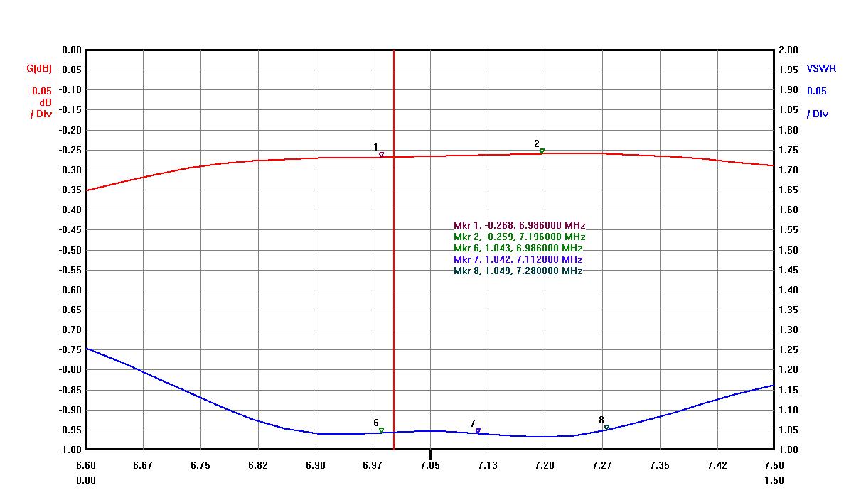
As it is 5th order BPF all numbers are quite good. Please, see some graphs below.
- Insertion Loss < 0.35 dB
- Band Isolation ( 80M > 60dB, 20M > 80dB, 15M >100dB)
- VSWR < 1.1 (RL > 26 dB)
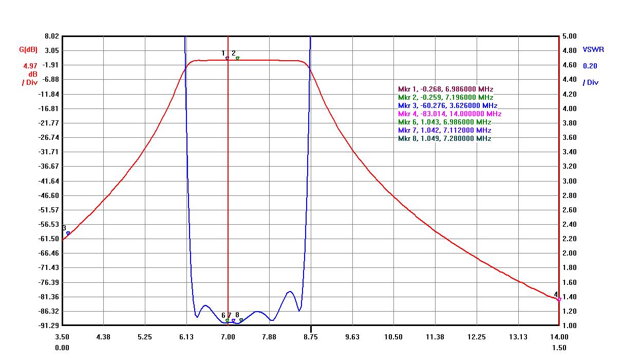
40M BPF In-Band graph below with VSWR and Insertion Loss.
- The next band was 80M BPF where I used Micrometals T200-2 toroids. Please, see some photo and graphs below.
The same 1500W output power test result was very good. Toroid cores did not get any heat with a little warm wires. I used 2 mm magnet wire. The same large doorknob capacitors used as it was for 40M BPF.
7″ or 8″ deep enclosure allows to install large doorknob capacitors with all available space for coils.
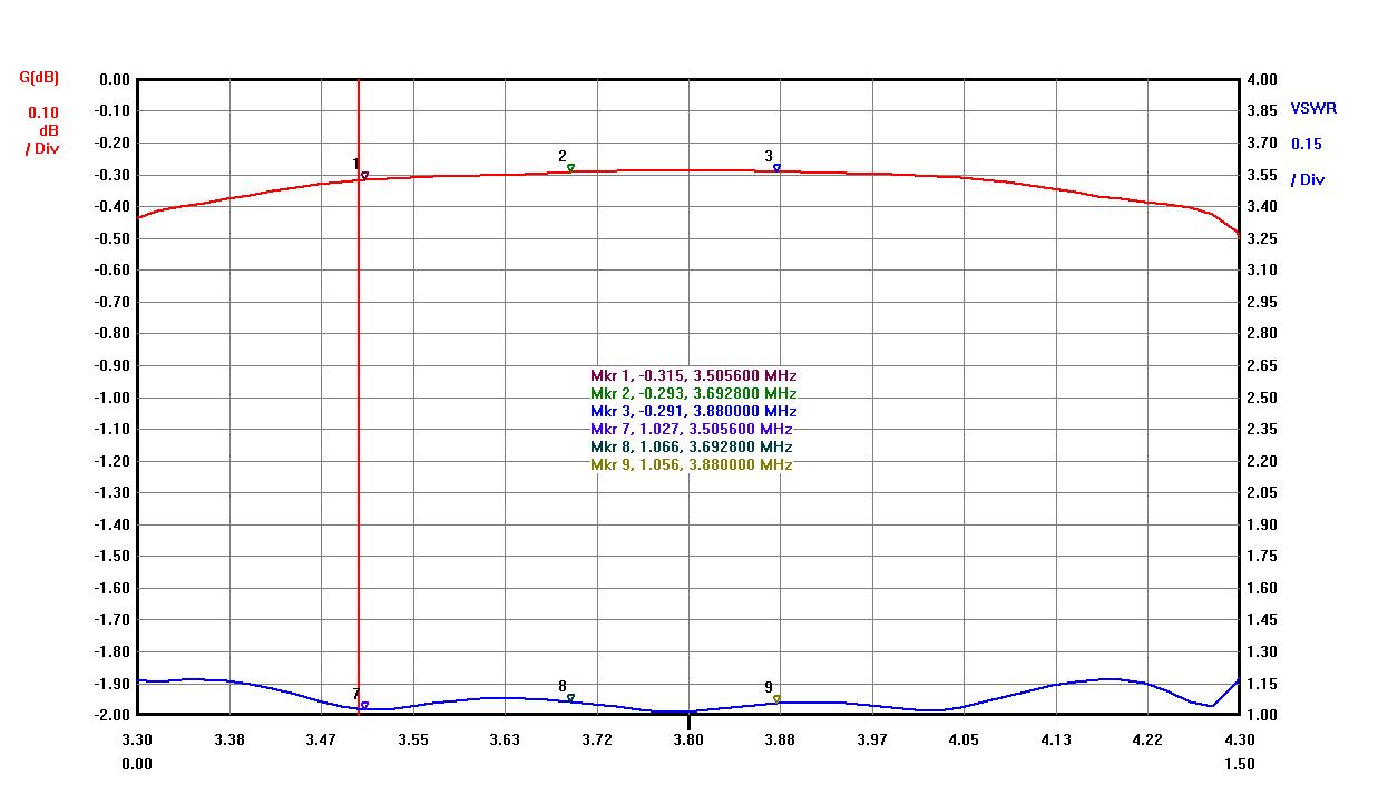
The first 80M BPF was built for 3.5-3.8 MHz to be used in Europe, but it can be tuned much wider up to 4 MHz if required with VSWR below 1.1.

- Insertion Loss < 0.35 dB
- Band Isolation ( 160M > 62dB, 40M > 70dB, 20M >100dB)
- VSWR < 1.1 (RL > 26 dB)

- For the 160M band a LPF (Low-Pass Filter) type was built. Result is very good with a very low Insertion Loss and very good band attenuation. Please, see some more information on a 160M LPF page.

- Insertion Loss < 0.15 dB
- Band Isolation ( 80M > 65dB, 40M > 80dB)
- VSWR < 1.1 (RL > 26 dB)

