- 200W Triplexer with BPFs
- 200W Triplexer
- 200W 10M Band-Pass Filter
- 10, 15, 20, 40, 80, 160 meter LP BPFs
Recommended Band Pass Filter (BPF) applied power with antenna VSWR <1.5:
- 200W CW/SSB ICAS
- 100W 100% Duty Cycle
Enclosure is Hammond 1411MU :
- 6″ x 3″ x 3″ (16 x 7.6 x 7.6 cm) without connectors
- 7″ x 3″ x 3″ (18 x 7.6 x 7.6 cm) with connectors
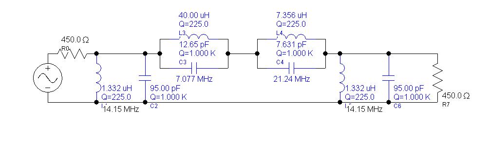
In general, schematics is the 3th order Cauer (Elliptic) type BPF.
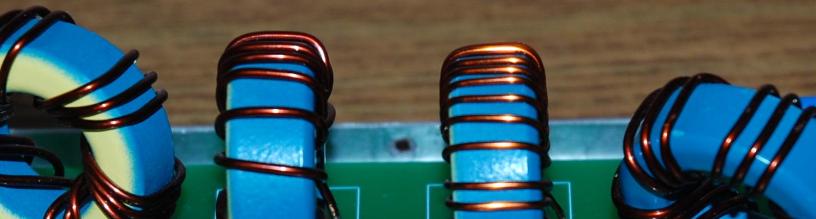
On a circuit above 1.332 uH is a trifilar winding coil on T130-17 Micrometals Iron Powder core. On a toroid I made 5 turns of a primary winding and other 10 turns as a secondary one over the initial 5 turns. The same technique used for a classic W3NQN BPFs.
As a result of that transformation, I designed the BPF for 450 Ohm( 50 * 9 =450). For 40 and 15 meter band LC traps the required values should be recalculated, multiplying by 9 a capacitor values and dividing by 9 inductance values.
These are a final values I used for 20M BPF:
- 12.65 pF * 9 = 113 pF
- 40uH / 9 = 4.44 uH (T130-17 30 turns)
- 7.63 pF * 9 = 69 pF
- 7.356uH / 9=0.81 uH (T130-17 12 turns)
For part values calculated above I used two/three in parallel ceramic capacitors and any Iron Powder cores can be used for coils , like T130, T106 or T94 of a size (types 2 or 17).
I used 95pF good quality and able to withstand 200W output power capacitors from Charcroft.com. A few good quality ceramic or Mica capacitors can be used as well.

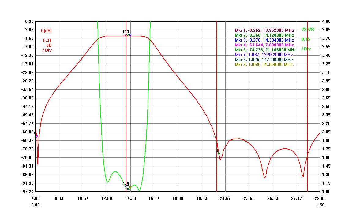
This BPF compare to a very popular W3NQN BPF has much better band attenuation (with the same number of required parts ).
Final results are very good for such a simple schematics.
- Insertion Loss < 0.3dB
- Band Isolation ( 40M > -60dB, 15M > -65dB, 10M > -60dB)
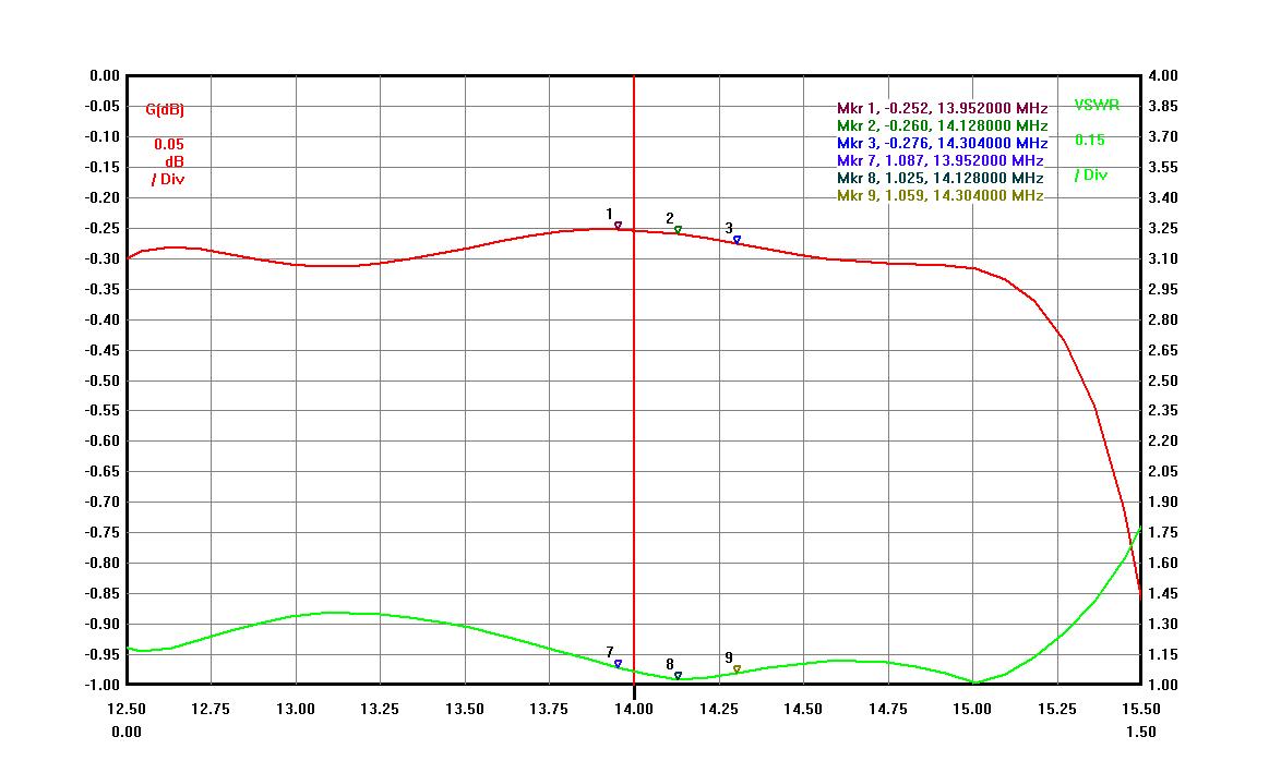
- VSWR <1.1 (RL >26 dB)
Below is a 20M BPF graph showing adjacent band isolation.
Below is a In-Band graph showing VSWR and Insertion Loss.