There are many different ways how to switch BPFs between two radios in a SO2R station setup. I would like to show some of them in this blog.
- All setup configurations are not a question for a low power setup, but as soon as power increased it is better off knowing what connection diagram would work better.
All of this discussion is about Tribander + Triplexer + BPFs configuration. If all antennas are single band antennas located on one or different towers the station setup can be quite different.
- Triplexer is a balanced filter system and all ports should see 50 ohm loads for the best performance and reliability, including unused ports.
- The most convenient way to achieve it is to have 50 ohm resistors in your antenna switch.
- You can build such an antenna switch on KK1L switch PCB (-67dB or better port isolation) or you can buy a 2×6 switch with interlocking system from RemoteQTH.com (-71dB or better port isolation) .
- It is a nice idea to use a radio band decoder, like this one from RemoteQTH.com or any other with a relay output, to turn ON a required High Power BPF cooling fan when a particular band chosen. This approach will decrease a fan noise and will allow all cooling fans last longer. With SO2R setup only two BPF’s cooling fans will be running simultaneously.
All ideas below is about how to achieve a higher band isolation if required.
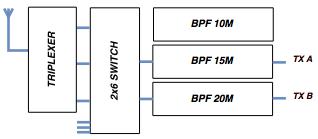
The first approach when amplifier connected to 2×6 switch and BPFs connected to the triplexer:

The second approach below shows 2×6 switch between triplexer and BPFs (Only two BPFs connected to simplify a required switching. If more than two bands used full diagram shown below):
The best way to use the 2nd approach is to have 6 Band BPFs set. Obviously, it is an easier way for a low power setup because many 6 band BPF units are available to buy. I never seen such a unit for a high power application and it is an easy to explain as 6 band high power BPF box could be a huge one by all dimensions.

I got more than -85dB isolation between any bands for the Triplexer + BPFs system measured without antenna switch attached.
Please, see two graphs below where connection diagrams above measured:

- KK1L antenna switch leakage (Green line) is for comparison. The first approach (Antenna switch installed before BPFs from TX side) band isolation is almost the same as KK1L antenna switch leakage line.
If BPFs installed before the antenna switch from TX side, the isolation level is below -90dB (the second approach).
It looks like the second approach is much better but I used only two BPFs connected to simplify the test. I need to use another switch or switches to connect three BPFs and switch them between two radios in my SO2R setup.
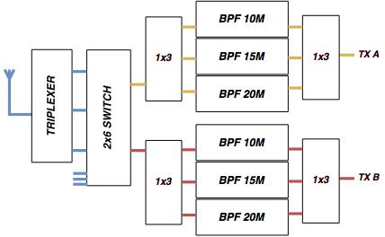
Please, see picture below as an example of a connection diagram for the first approach. In a real application, it can be used 1×6 switches instead of 1×3.
I am using a combination of 1×3 (or 1×6) and 1×2 switches and not 2×6 switch which as from my measurements limited the isolation by KK1L 2×6 switch (-63dB).
- The 2×6 switch replaced by a combination of different switches because it’s easier to achieve a good port isolation for 1×2 switch than for 2×6 switch.

- Radio’s isolation limited by 1×2 switches and not by 1×3 switches as 1×2 switch shares its ports between radio A and B.
The picture below is a typical 1×2 switch which can provide TX A and TX B port isolation up to -90dB level.
If triplexer used, all unused port should be connected to a 50 Ohm load. In this 1×2 switch Relay 3 is to connect BPF port to the 50 Ohm load.

Below is a diagram with only 1×2 switches with a very good result achievable with this circuit.
- The first switches after BPFs should have built-in an extra relay for 50 Ohm load for unused triplexer ports. The best way to install 50Ohm load is to have them inside the Triplexer or BPFs.
- Inside the 1×2 switch DPDT relay can be added for interlocking function when the 1st radio takes the band making it unavailable for the second radio until switching to another band.
- You can consider this switch as a 2×5 switch where 3 ports dedicated to higher bands and 2 ports dedicated to low bands.
This configuration allows any radio to be on any band available.

The diagram below is a little different in a way where 10 and 20 meter bands dedicated to different radios in SO2R setup and 15M band is a switchable between radios.
Using high isolated 1×2 switches a very good 2×6 switch can be built.
- This 2×6 switch built as a combination of 1×2 switches and can have a very good band isolation and can be used with Triplexer and Diplexer (or without them) as well.
- 160M and 80 meter bands cannot be used both radios the same time as they connected to a Radio B. If another 2×1 module added (the same approach as used for 15M band) then 160M or 80M band can be switched between radios.

Below is a full diagram, including low bands as well.
- 10 and 40 bands dedicated to Radio A, 20 and 80 meter bands dedicated to a Radio B and 15 and 160 meter bands are switchable between radio A and radio B.
- The bands on the diagram switched the way that harmonics bands like, 10 and 20 or 40 and 80 in a different 1×2 switches.
- This approach has less flexibility ( not allow every radio to go to any band) but allows having much better band isolation.
- Personally, I see no problem to dedicate some band antennas to a particular radio instead of a common 2×6 approach where every antenna can be switched to any radio.

Please, see picture below as an example of a connection diagram for the second approach mention in the beginning of this discussion. In a real application, it can be used 1×6 switches instead of 1×3.
The diagram looks more complicated than the first one.

The same requirements is for 1×2 switch as this switch will set the achievable isolation level between radio A and B. Such a setup diagram has many switches and connection cables around.
- For 1×3 or 1×6 switches leakage is not a problem as those switches do not share their ports with another radio.
I found some 2×6 switches capable of isolating ports to a level of -70-75dB but it is still lower than that isolation achieved by direct connection Triplexer to BPFs.
I am talking about high power application where level of -80dB was a goal for a station setup.
I see two possible solutions with situation I described above:
- I have to build a switch with better than -80dB port isolation.
- I have to use two sets of BPFs with simple and widely available 1×6 switches connected for each radio.
The first solution is not an easy way to solve the problem as I’ve never seen an 2×6 antenna switch delivering -80dB between band ports, especially using relays for a station automation. So, a combination of switches should be used.
The second solution is no problem but I have to have the second set of high power BPFs. With this approach both radios will be completely separated and internal port leakage inside the switches is not a problem any more.
- The setup diagram above is not limited by switches isolation level as all of them do not share their ports between radios. From my previous measurements 2×6 antenna switch is not a limitation factor if installed after BPFs.
My current low power SO2R station setup built using two 5B4AGN design BPF sets and I have very good band isolation between transceivers.
The graphs below shows (brown line) my 100 watts two sets of BPFs connected to the high power triplexer to make comparison the same. The isolation lower than my high power setup as W3NQN BPFs provided lower band attenuation than my high power BPFs.

The low power setup isolation is better than -85dB and line on the graph is well below the KK1L antenna switch leakage line. The W3NQN BPFs switched by two relays for every BPF and when not in use they connected to the ground.
The original W3NQN BPFs + Triplexer band isolation is around -60-70dB. My BPF set are better as I made some modifications to a Cauer (Elliptic) type.
I used two sets for convenience only as KK1L antenna switch is perfectly suitable for a low power setup. 5B4AGN design BPF set contains band decoder I am using to control my 2×6 antenna switch.
- Diagrams with a single BPF set required a careful switch consideration as some of them can be an isolation limitation factor (those switches sharing band ports between radios).
- Diagram with two BPF sets can provide a complete radio separation and a relay switch specification is not a factor for a full performance.
Another recommendation is to keep all unused triplexer ports loaded with 50 Ohms because triplexer is a balanced filter system and it expected to have all ports loaded properly.
One of the most convenient and easiest way to have this functionality is to have it as a built-in an antenna switch. Something like on a picture below or it can be done with some external relays. You can see that by default unused port always connected to a 50 Ohm resistor, so if the triplexer or BPF connected to the port it always sees the proper load.
- You can build such an antenna switch on KK1L switch PCB (-67dB minimum port isolation) or you can buy a 2×6 switch with interlocking system from RemoteQTH.com (-71dB minimum port isolation) .
Below is a diagram used by NP2N during 2017 ARRL DX CW with VA6AM high power triplexer. Used A/B switches made by Top Ten Devices have a very good port isolation (better than -80dB) .
The same idea can be used to build a high isolation switch circuit for SO2R, MS, M2 or MM stations. As always for a proper triplexer usage the first switches after BPFs should have 50 Ohm resistors built into the switches to keep all unused triplexer ports properly loaded.

