
I did not get expected result from the design and I will keep on trying some different ideas before I publish it here.
- If you interested to try this design I have a few boards left and I sell it at cost for $17.00 dollar each. It can be built using 5 or 3 relays per band. Three relays would have less contact capacitance and a higher band isolation achievable. For lower power setup this board will work perfectly.
There are many 2×6 switches existed but I wanted to design and build my own.
- It must be a high band isolation switch to meet my Triplexer with BPFs specification
- It must provide 50 Ohm load to every unused port for a triplexer setup
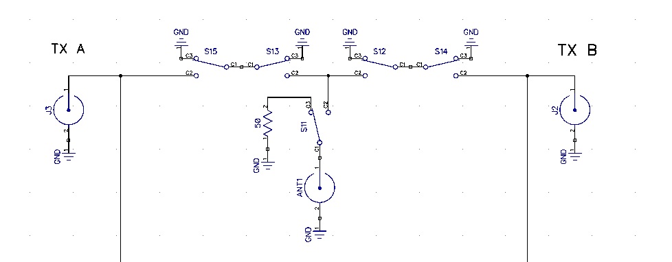
Below is a partial schematics of one band of the 2×6 antenna switch.
- There are two-relays-in-series to each radio leg to increase an isolation.
- There is an extra relay to control 50 Ohm resistor.
- There are 5 relays per band (Usual approach is to have 3 relays for the design)
The photo below is the first assembled board before going into an enclosure.
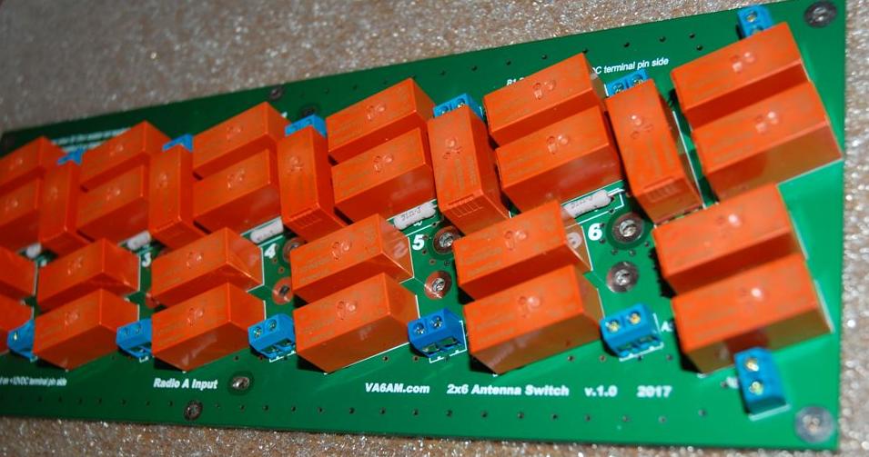
Four relays in a row is a good idea to increase an isolation…if it is not a 2×6 switch.
All capacitance between relay contacts will be summed up for all 6 bands and as a result the Radio port isolation degraded. So, for this design a right relay type should be chosen.
This particular relay I used has -37dB of isolation between contacts on 28MHz. Some relays I have for a test close to -45dB of contact isolation but only 10A relays. The better the isolation number the less capacitance between relay contacts. I should have tried those 10A relays instead of 16A relay I used. 10A relay is good one for a few kilowatts with VSWR < 1.5
This was my mistake of used relay type soldered into the board and as a result lower number than that I was expecting.
I would like to check more relays before I make another try for the board design.
