Direct Links: 10–15–20–40–80–160 – 3000W Triplexer
The project idea is to design and build a Triplexer with BPFs set for 3000 watt amplifier output power.
Some short specification of the 3000W set:
- BPFs are 5th order Chebyshev type with isolation > – 55dB (mostly better than -60dB)
- BPFs together with Triplexer > – 85dB
- More than -100 dB of isolation between 10 and 20 meter bands (with Triplexer)
- The Triplexer + BPFs set Return Loss > 25dB
- The Triplexer + BPFs set Insertion Loss below 10M – 0.27dB, 15M – 0.4 dB, 20M – 0.4dB
Recommended BPF Power with antenna VSWR < 1.5:
- With 50 CFM air cooling: 2500W CW/SSB
- With 100 CFM air cooling: 3500W CW/SSB
- Without fan installed: 1500W CW/SSB PEP
Enclosure is Hammond 1411ZU:
- Without Fan – 17″ x 5″ x 4″
- With Fan Installed – 18.5″ x 5″ x 4″

With total band isolation better than -85dB it can be used up to 6000W by Isolation level . My own “smoke” test done with 3000W. As per my best knowledge, a few 3000W Triplexer with BPF sets used with OM3500 amplifier without any issues.
When using Triplexer with connected BPFs I would recommend to use devices below in your station setup:
- The interlocking system inside your antenna switch to prevent from switching both radios to the same band.
- Coax cables between Triplexer and BPFs should be as short as possible.
- The high SWR protection unit. It can be built-in inside your amplifier or it can be a separate SWR/Power meter with PTT control.
- Antenna switch with 50 ohm load available from KK1L switch PCB (-67dB or better port isolation) or you can buy a 2×6 switch with interlocking system from RemoteQTH.com (-71dB or better port isolation) .
All graphs shown below taken using UHF M-M adapter. Please, see diagram.
- Every unused band port must see a 50 Ohm load for the triplexer best performance and reliability.
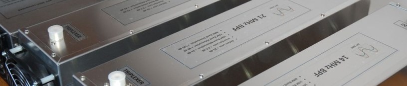
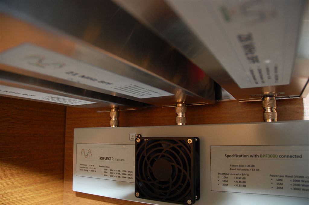
Photo below shows how I connected my prototype triplexer with BPFs using M-M adapter. Please, see some Installation options here. BPFs installed vertically and Triplexer is in front of them on a desk/shelf.
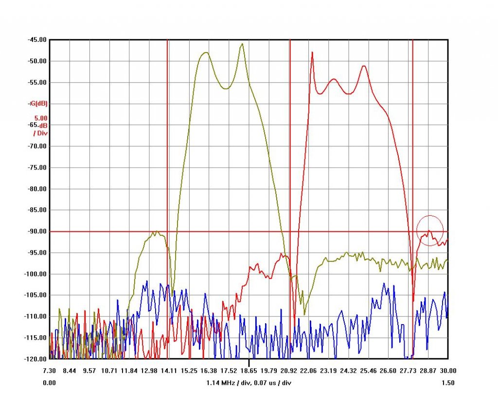
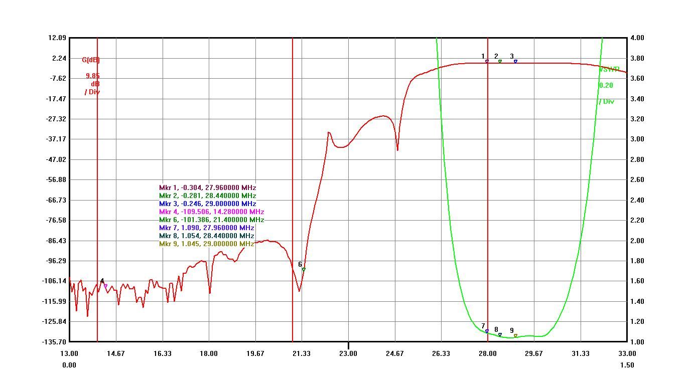
Below is a graph with measurement of isolation levels between bands.
VNA was connected to two band ports and measured 10-15, 10-20 and 15-20 band combinations.
- The Blue line is isolation between 20 and 10 meter bands. It is well below -100 dB isolation level.
- The Red line is isolation between 10 and 15 meter bands. The 28.9MHz peak is the minimum of -89 dB isolation level.
- The Green line is isolation between 20 and 15 meter bands. It is better than -93 dB isolation level.
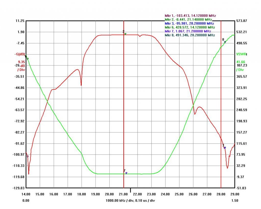
20M band BPF + Triplexer (all BPFs attached):
- Insertion Loss < 0.40dB
- Band Isolation ( 15M > 95dB, 10M > 110 dB under VNA noise floor, 40M > 67dB)
- VSWR< 1.09 (RL > 27 dB)

15M band BPF + Triplexer (all BPFs attached):
- Insertion Loss < 0.45dB
- Band Isolation ( 20M > 88dB, 10M > 88 dB)
- VSWR< 1.09 (RL > 27 dB)
10M band BPF + Triplexer (all BPFs attached):
- Insertion Loss < 0.55dB
- Band Isolation ( 15M > 88dB, 20M > 100 dB)
- VSWR< 1.1 (RL > 26 dB)
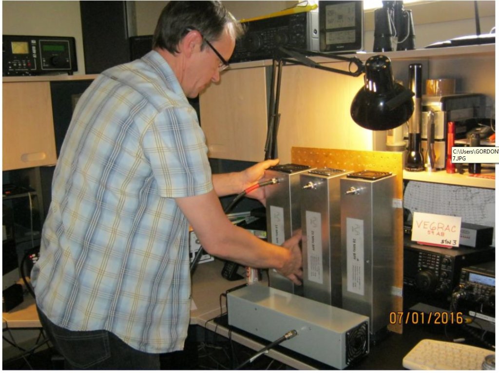
It was less then 10-15 mV (measured by Tektronix oscilloscope) to 15 and 10 meter bands with more than 3000 watts applied to 20M band BPFs in CW mode (as it was connected on the picture above).
All test done using my GS-35B amplifier at power level of 1500 watts and with help of VE6SV on power level of 3000 watts. Gordon has a wonderful MS station setup with everything available for a real testing. Thanks a lot!
- RX IMD for Triplexer with BPFs connected is better than -20dBm level at any band ports.
The numbers above are without an antenna switch attached. Please, read a switching consideration here.
- The power smoke test shows that Triplexer + BPFs design is good at 3000 watt power level to provide a sufficient level of band isolation. Please, see High Power BPF page for some power restrictions.
